SiplaceX4_en.pdf - 第533页
1 - 28 S tudent Guide SIPLACE X 1 1 Sitest Edition 09/2005 28 T win head height: Calibrate Head heigh t mean to determine Z-Zero po int correction. 11 Fig. 1 1.2 - 15 T win head height Sequence: – move to zero pulse – se…
1 - 27
Student Guide SIPLACE X
Edition 09/2005 11 Sitest
27
PCB camera - Component camera offset: 11
– At the measurements for Segment offset bottom (II) we calibrate the PCB -> component cam-
era offset with Segment 1:
– The distance in X- and Y- direction of the camera centers is determined in µm.
– The camera center of the PCB-camera is the reference.
– This distance is saved in REAL.MA at ‘Kopfoffsets’ at Kopf 1 (or in future Kopf 2) Kopfoffset_X
/..Y. (The Segmentoffset bottom of Segment 1 is 0)
– The Segment offsets of the other 11 (5) Segments are saved, as a deviation to segment 1, in
PIP_OFF.MA.
– For the Segment offset bottom the values are without limits.
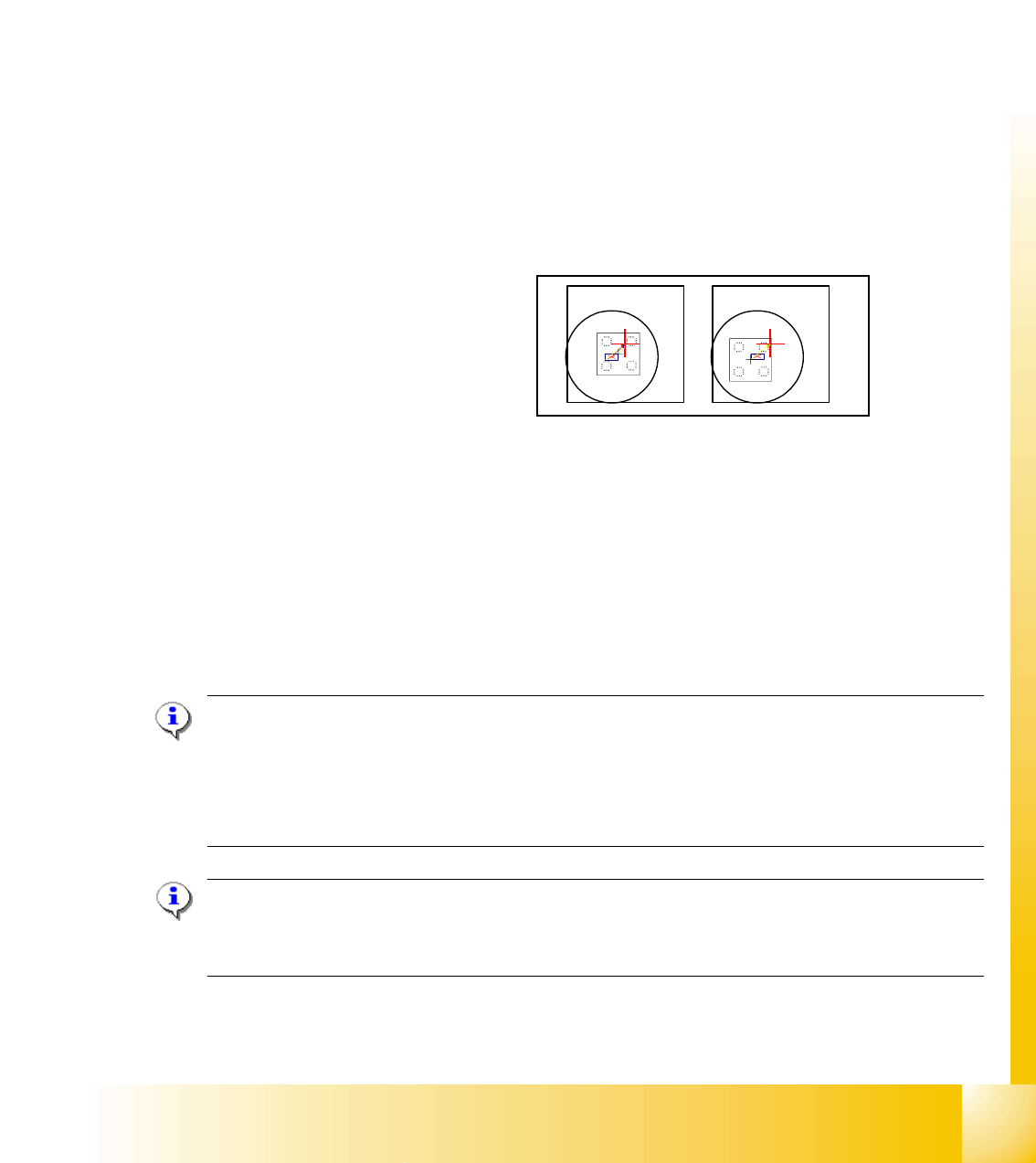
Sequence segment offset top (I): 11
Fig. 11.2 - 14 Princple picture of a calibration tool in the camera in 0° (left); in 180°(right).
– After Segment offset bottom (II) we calibrate with Segment offset top (I) for C&P DLM 2 seg-
ments :
– the deviation in X- and Y-direction of the turning axis of the segments referring to the camera
center of comp. camera in µm.
– The Measurement is done in 0° 180° respective 90° 270°.
– The Segment offset values are saved in PIP_OFF.MA.
Note:
For the segment offset I (top), the size of deviation shouldn‘t be larger than 450 µm for the seg-
ments and the deviation between the segments shouldn‘t be larger than +/- 150 µm.
The segment offset II (bottom) should not be larger than +/- 200µm. The deviation of the segments
should not larger than +/-150 µm.
Note:
The segment offset II (bottom), from the first segment is always 0 that is the reference value to the
other segments.
1 - 28
Student Guide SIPLACE X
11 Sitest Edition 09/2005
28
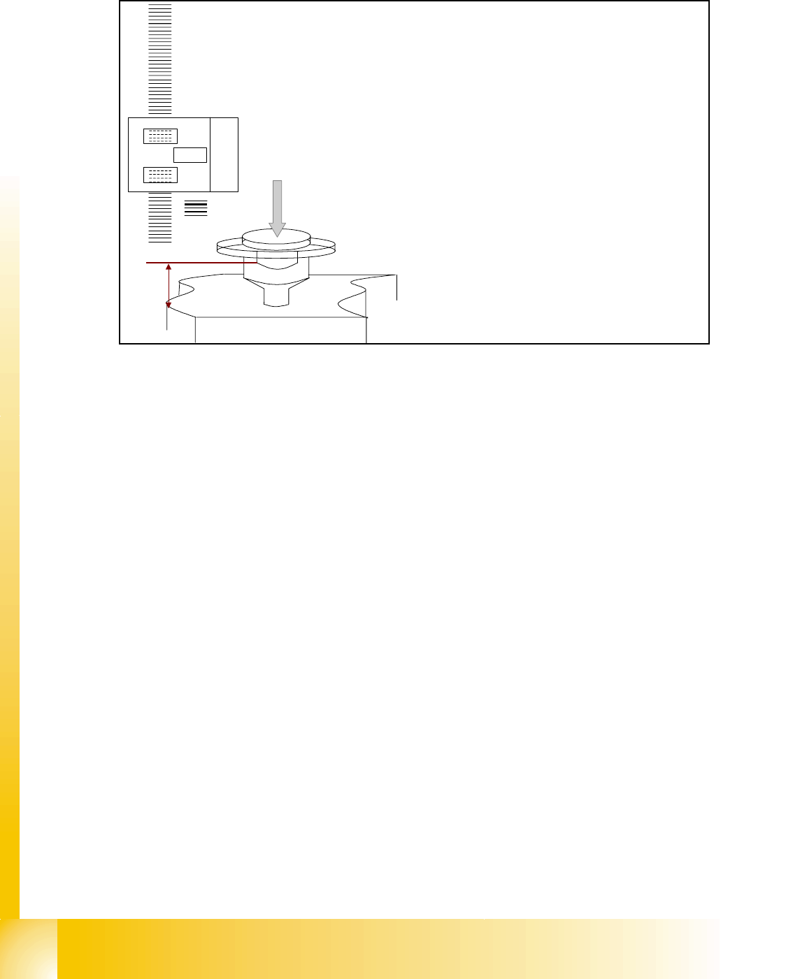
Twin head height: Calibrate Head height mean to determine Z-Zero point correction. 11
Fig. 11.2 - 15 Twin head height
Sequence:
– move to zero pulse
– set the position counter to 0
– move with 517 nozzle to the transport rail
– measure actual position
– subtract ‘Kopfhöhe’ head height from Ideal.ma (65500)
– subtract theoretical nozzle length
– is zero point correction Z-pos.act. -nozzle length -head height = 0-corr.
IC camera: 11
– After measuring the head height of TWIN head (Z-axis zero point correction) the TWIN -IC
camera is calibrated.
– The first measurement is the focus level. That means, the twin head move with the Z-axis of
the cover from the stationary camera. (This height is the centering height for bottom side of
components.)
– The Pixel size in µm of the camera is determined next. Saved as:/XU_Pixel / YU_Pixel/ of cam-
era 11(in 79000 nm).
– The camera center of the TWIN- IC-camera refer to the zero point of the machine (X- / Y-
counter zero position).
A
B
‘
1
5
4
3
2
1. Incremental scale on the Z-axis
2. Incremental encoder fixed
3. Top of the conveyor rail
4. Head height
5. Nozzle lenght

1 - 29
Student Guide SIPLACE X
Edition 09/2005 11 Sitest
29
Saved are all this data and coordinates in: KAM_DAT.MA in Data bloc camera 11: (for gantry 2)
Kamera_Position_X / 1483500, Kamera_Position_Y/ 1370500, Kamera_Offset_Z/ 5000
Calibration data of IC camera saved in mapp_pkt.ma file.
– Calibration IC camera position fiducial
FC camera: (Option) 11
– After measuring the head height of TWIN head the TWIN -FC camera is calibrated.
– The first measurement is the focus level. That means, the twin head move with the Z-axis of
the cover from the stationary camera. (This height is the centering height for bottom side of
components.)
– The Pixel size in µm of the camera is determined next. Saved as:/XU_Pixel / YU_Pixel/ of cam-
era 15(in 19600 nm).
– The camera center of the TWIN- FC-camera refer to the zero point of the machine (X- / Y-
counter zero position).
Saved are all this data and coordinates in: KAM_DAT.MA in Data bloc camera 15: (for gantry 2)
Kamera_Position_X / Kamera_Position_Y/ Kamera_Offset_Z/
– Calibration IC camera position fiducial
Twin head segment offset bottom at segment 1 and 2: 11
– The segment offset determined the middle of the segment to the PCB camera. That means the
D axis, center of sleeve of the TWIN (IC) -placement head refer to the camera center of PCB-
camera. This measurement is only done in the lower position so the result is saved as an
offset "2" at the head.
The coordinates saved in PIP_OFF.MA at Data bloc /Pipetten-Offsets unten Kopf 2/ Pipetten-Off-
sets unten Segment 1(2) Offset_X /Offset_Y /
Nozzle changer (C&P head, Twin head): 11
Note: Precondition for calibrate the nozzle changer is to check or determine the zero point cor-
rection for the D - Axis Twinhead, the configuration of the nozzle changer and the fill level.
– Each nozzle magazine has an fiducial which will recognize during the calibration procedure at
first.
– After that, the machine recognize the two fiducial of the holder from the magazine on the left
and right side.
– optional, calibrate the pick up height from the nozzle changer.
– optional, calibrate the reject position from the nozzle changer, necessary to reject nozzle which
are defekt.
Calibrate closed vacuum: 11
This function measure onto the fixed conveyor rail with the nozzle 518 the closed vacuum values
of the vacuum system for the segment 1 and 2.