SiplaceX4_en.pdf - 第549页
1 - 6 S tudent Guide SIPLACE X 12 Siplace X - Head M odularity Edition 09/2005 6 12.1.2 Head exchange 1. Make a backup f or the exi st machine conf igurat ion. 2. Machi ne data - backup wi th the Sit est and creat e a fo…
1 - 5
Student Guide SIPLACE X
Edition 09/2005 12 Siplace X - Head Modularity
5
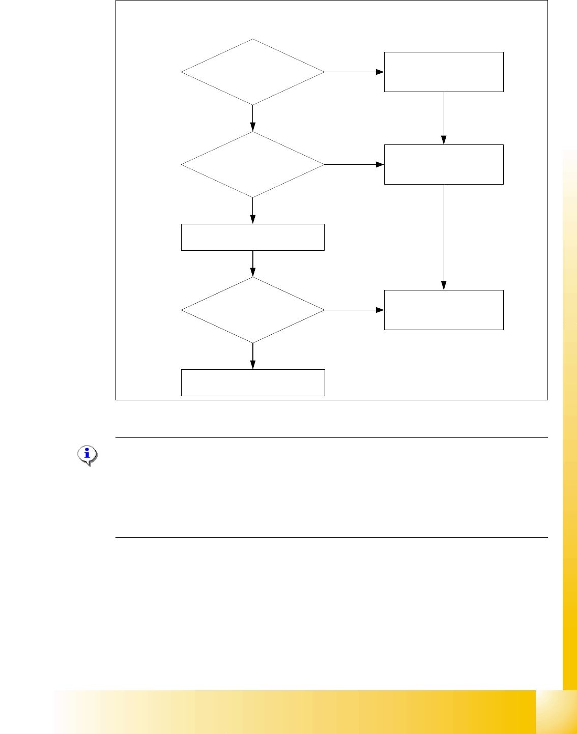
Fig. 12.1 - 3 Means of deciding between 12 segment C&P head or 6 segment C&P head w/o DCA camera
Please Note:
For the Option Head Modularity please use the retrofitting instruction "Head Reconfiguration kits
00119721- Twin Head Reconfiguration Kit X-Serie
00119760- 12-Seg. C&P Head Reconfiguration Kit digital
00119761- 6-Seg. C&P Head Reconfiguration Kit digital
00119762- C&P20 Head Reconfiguration Kit
On the 6 segment C&P head is a high resolution camera as standard mounted, so you can use
this camera on the 12 segment C&P head for 0201 components and Flip chip‘s.
Component size > 18,7x18,7mm
Component height > 6mm
?
BE weight > 2g?
0201 or BARE DIE
Flip chip placement?
6 segment C&P head
6 segment C&P head with standard
Camera or
12 segment C&P head with the
camera from the 6 C&P head (DCA)
6 segment C&P head
Yes
Yes
Yes
12 Segment C&P head
No
No
No
12 Segment C&P head with
standard camera
Deciding factors about the choice of the C & P heads and the camera types.
1 - 6
Student Guide SIPLACE X
12 Siplace X - Head Modularity Edition 09/2005
6
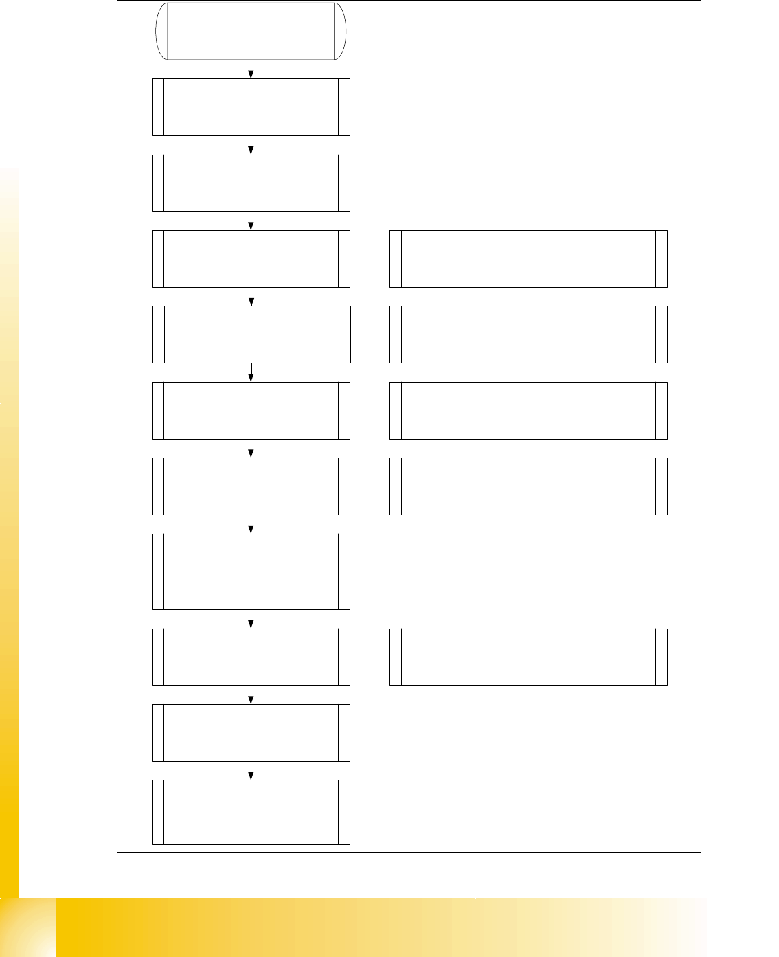
12.1.2 Head exchange
1. Make a backup for the exist
machine configuration.
2. Machine data - backup with the
Sitest and create a folder
e.g. Backup and store the folder
SRCMA.
4. Confirm the configuration,
machine will shutdown
automatically
Switch off the machine!
6. Mechanical works:
Mount the Head, adapterboard
and Nozzlechanger.
7. Switch ON the machine
Look to the error messages
Set the nozzle on the head and
check the nozzle changer.
Note: Save the zero point correction from the
EEPROM to the Achsver.ma.
Check the firmware!
8. Siplace Pro computer:
Make a copy of the exist basic set
up and configure into the copy the
new head type and
nozzlechanger
Note: As a result the new configuration will be
send to the station.
9. Siplace Pro computer:
Send a placement program, e.g.
with one component to the
station.
10. Station:
Check the axis dynamic and
calibrate all heads and cameras.
11. Station:
Start the production.
Note: Stop the current job from Siplace Pro
before you shutdown the machine.
5. Mechanical works:
Head, Nozzlechanger and
adapterboard exchange.
Note: Don`t change the adapterboard if you
change from C&P6 < -- > C&P12 head. Change
the Servo amplifier and don`t forget the DC/DC
converter for C&P 20 head.
Note: Preparations of the head plate (sealing with grub
screw, attention different length of the head screws)
Height adjustment nozzlechanger and different pressure
air supply for C&P20 head!
C&P20 X-Feeder Docking unit
3. SITEST: Machine configuration
(Head type, nozzle changer,
cameras).
1 - 7
Student Guide SIPLACE X
Edition 09/2005 12 Siplace X - Head Modularity
7
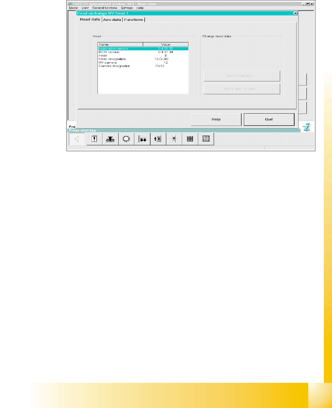
12.1.3 Menu Head exchange
Fig. 12.1 - 4 Menu "Head exchange" --> "Head data"
Versions information and head type will be read automatically from the imtermediate board. With
the first boot sequence after the reconfiguration of the head types could be appears the message
of changing head types then the Buttons on the right site are active. Now you can edit and corret
the head typ and camera typ.
Overview head type numbers: 12
Head number ‘5’ is C&P 12
Head number ‘6’ is C&P 6
Head number ‘4’(7) is TWIN head
Head number ‘8’ is C&P 20