SiplaceX4_en.pdf - 第554页
1 - 1 1 S tudent Guide SIPLACE X Edition 09/2005 12 Siplac e X - Head Modularity 11 12.3 Head modularity T w in Head to C&P Head Fig. 12.3 - 1 Flowchart Head exchange T win head to C&P 1. D a ta b a c k u p Machi…
1 - 10
Student Guide SIPLACE X
12 Siplace X - Head Modularity Edition 09/2005
10
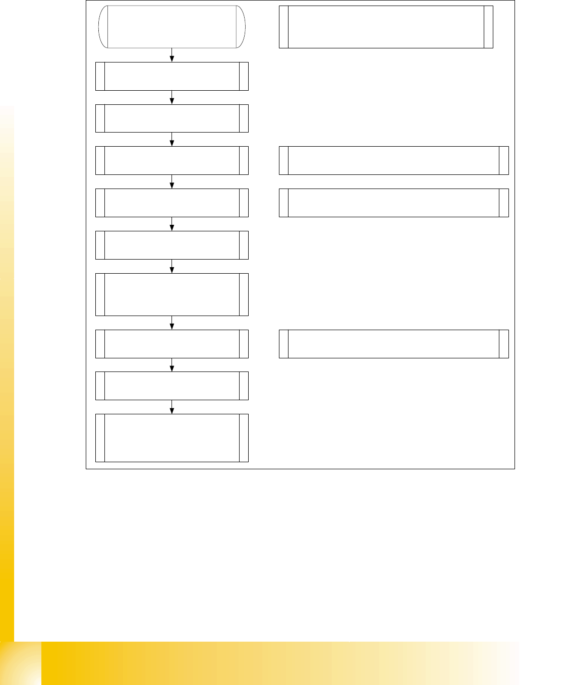
12.2 Head modularity C&P Head to Twin Head
Fig. 12.2 - 1 Flowchart Head excange C&P to Twin Head
1. Data backup
Machine configuration
2. Remove C&P head with head
adapter.
3. Remove nozzle changer for
C&P head.
4. Mount stationary IC and/or FC-
camera.
Note: Twin head not possible in placement areas with
two gantries.
Exchange the docking unit to mount the stat. cameras
5. Mount Twin head with head
adapter.
6. Mount nozzle changer Twin
head.
Note: Check the DIP -Switches. Change the grub
screws into the correct position.
9. Calibrate Twin head and
cameras. (Mapping)
10. Change the machine
configuration in Siplace Pro.
8. Check the Twin head
specific data and make a
Firmware download.
Note: Sitest „Head type“ Read data from the head
Eprom and check the machine data.
7. Mounting the servo boards for
the Twin head (Axisunit) and
switch the Hotlink-cable for the
cameras (Computer unit).
Note: SITEST Machine configuration
Confirm the configuration, shutdown and switch
off the machine
1 - 11
Student Guide SIPLACE X
Edition 09/2005 12 Siplace X - Head Modularity
11
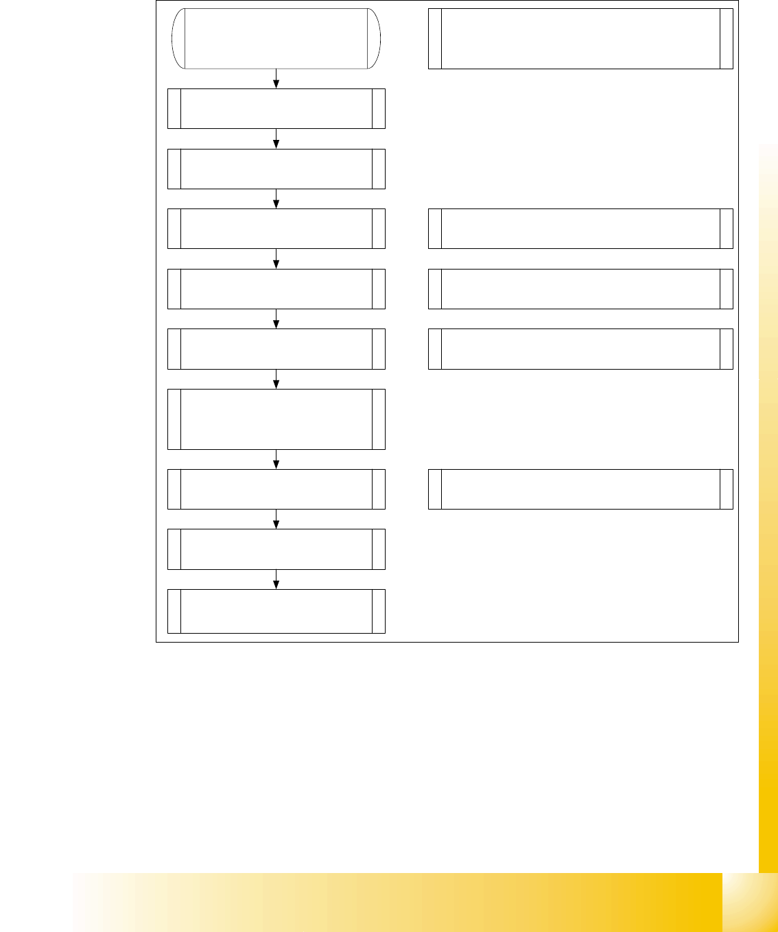
12.3 Head modularity Twin Head to C&P Head
Fig. 12.3 - 1 Flowchart Head exchange Twin head to C&P
1. Data backup
Machine configuration
2. Remove Twin head with head
adapter.
3. Remove nozzle changer for
Twin head.
4. Remove the stationary IC and/
or FC- camera.
Note: Remove the camera "HEADCRASH".
For exchange the stat. Cameras you have to
disassembly the docking unit.
5. Mount C&P head with head
adapter.
6. Mount the nozzle changer C&P
head.
Note: Check the DIP -Switches.
Note: Depend on the head pressure air supply
2,5 bar C&P6/12 or 4,5 bar C&P20.
Assembly docking unit for X-Feeder if C&P20
9. Calibrate C&P head and
cameras (Mapping).
8. Check the C&P head
specific data and make a
Firmware download.
Note: Sitest „Head type“ Read data from the
head Eprom and check the machine data.
7. Mounting the servo boards for
the C&P head (Axisunit) and
switch the Hotlink-cable for the
cameras (Computer unit).
10. Change the machine
configuration in Siplace Pro.
Note: SITEST Machine configuration
Confirm the configuration, shutdown and switch
off the machine

1 - 12
Student Guide SIPLACE X
12 Siplace X - Head Modularity Edition 09/2005
12
12.4 Head modularity C&P 6/12 to C&P 20 Head
Fig. 12.4 - 1 Head Modularity C&P 6/12 to C&P 20
1. Data backup
Machine configuration
2. Remove C&P 6/12 with head
adapter.
3. Remove nozzle changer for
C&P 6/12 head.
4. Mount C&P head with head
adapter.
5. Mount the nozzle changer
C&P 20 head.
Note: Check the DIP -Switches.
Note: Change the pressure air supply 2,5 bar
C&P6/12 to 4,5 bar C&P20.
Assembly docking unit for X-Feeder if C&P20
8. Calibrate C&P head and
cameras (Mapping).
7. Check the C&P head
specific data and make a
Firmware download.
Note: Sitest „Head type“ Read data from the
head Eprom and check the machine data.
6. Mounting the servo boards for
the C&P 20 head (Axisunit) and
the Hotlink-cable for the cameras
are OK(Computer unit).
9. Change the machine
configuration in Siplace Pro.
Note: SITEST Machine configuration
Confirm the configuration, shutdown and switch
off the machine