SiplaceX4_en.pdf - 第595页
1 - 28 S tudent Guide SIPLACE X 13 MTC 2 Edition 09/2005 28 13.2.6 Inst allation MTC 2 Note: If you change the componen t changeover ta ble to a MTC at location 2 and/or 4 you have to change the whole docking unit (W ork…
1 - 28
Student Guide SIPLACE X
13 MTC 2 Edition 09/2005
28
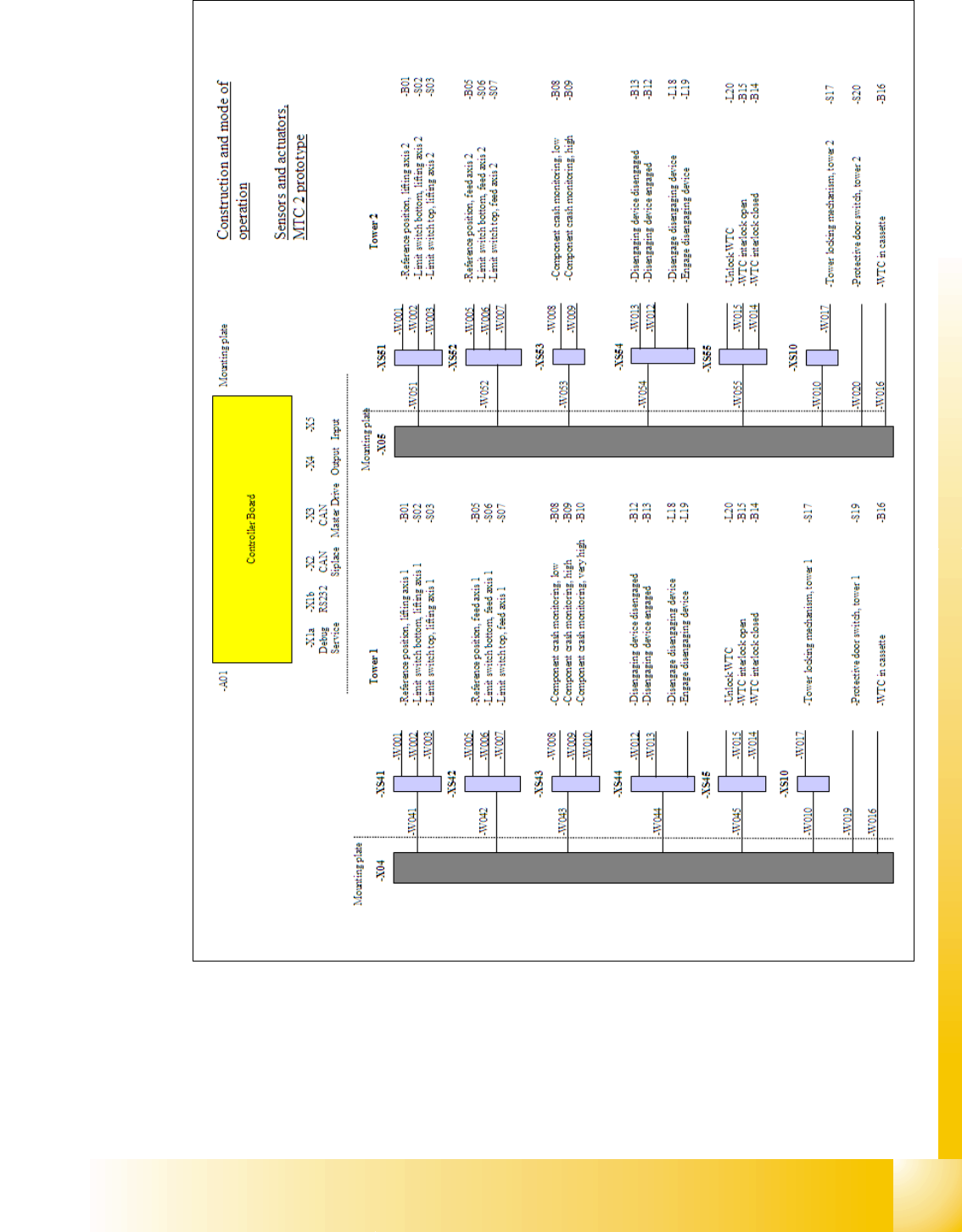
13.2.6 Installation MTC 2
Note:
If you change the component changeover table to a MTC at location 2 and/or 4 you have to
change the whole docking unit (Working time approx. 1,0 hour).
Installation manual: MTC 2 to Siplace HF/HF3 or Siplace X (00193897-01.pdf / Deutsch, Eng-
lisch)
In the installation manual the modification is described for a HF machine. The cables aren't avai-
lable to newer HF/HF3 and at the SIPLACE X machines at the side of the machine.
All cables which go to the docking unit are in the machine frame and must be attached according
to the cable name.
Note: The HF machines with the series number A 001 and the SIPLACE X machines are equip-
ped with a "One Wire bus" which is integrated in the Can bus. If you install on these machine a
MTC2 you have to make an additional CAN Bus link before the cable go in the docking unit of the
MTC. The reason is, that the signals of the CAN Bus go in and come out of the docking unit not
the One Wire signals.
The CAN Bus link is necessary on location 2 or 4, if you install an MTC on this location.
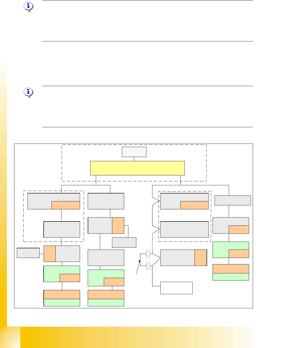
Abb. 13.2 - 7 Zusätzliche CAN Bus Brücke beim Einbau eines MTC 2
SMP BUS
MC
MC
Computer Unit
Main Distributor Sector 2
COM UNIT
x6pn
x7pn
CAN Bus
Axis unit
PA 2
COT 3
Tape cutter
One Wire
"Switch"
CAN Bus cable with "One Wire"
Change to MTC
Tape cutter
Location 2
Vision
Control unit
Sector 2
Nozzle
changer A/B
One Wire
Switch
CAN I/O
Main Modul
Sector 2
One Wire
"Control unit"
120 Ohm
Terminator
Axis unit
PA 1
CAN Bus
CAN E/A
Modul
Sektor 4
CAN E/A
Modul
Sektor 4
CAN E/A
CAN I/O
SUB Modul
Sector 4
COT 1
Tape cutter
SUB Distributor Sector 4
One Wire
"Control unit"
Trailing
Interface
Gantry 1
One Wire
"Switch"
CAN Bus cable
with One Wire
COT 4
Tape cutter
Vision
Control unit
Sector 4
Trailing-
Interface
Gantry 4
One Wire
"Switch"
Temperature sensor
One Wire
"Head interface"
Temperature sensor
One Wire
"Head interface"
Transport
Control
unit
Nozzle
changer A/B
One Wire
Switch
One Wire
Switch
Trailing-
Interface
Gantry 3
Temperature sensor
One Wire
"Headinterface"
CAN
Bus link
One Wire
"Switch"
1 - 29
Student Guide SIPLACE X
Edition 09/2005 13 MTC 2
29
13.2.7 General works before starting the MTC 2
– Setting the basic height
– Installing the intervention guard for the lifting axis
– Docking
– Undocking
– MTC 2 handling , Refilling concept
Note:
see User manual 00193634-01_de.pdf / 00193635-01_eng.pdf.
13.2.8 Placement functions of the MTC 2
13.2.8.1 Main view with MTC 2
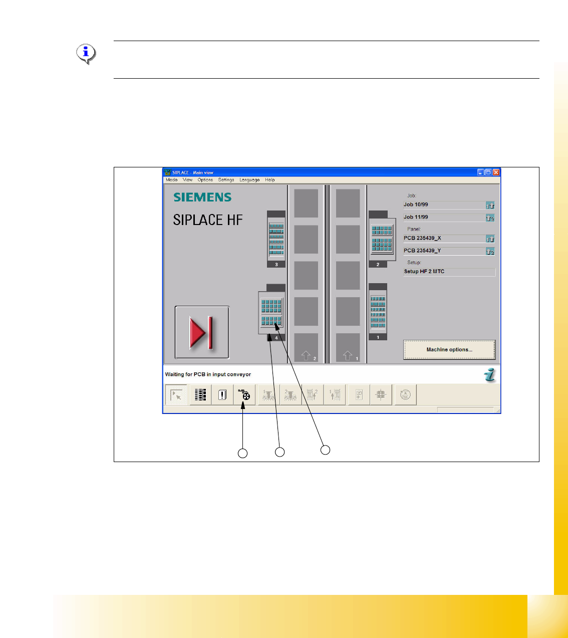
Fig. 13.2 - 8 Main view of the SIPLACE HF with MTCs on locations 2 and 4
Key
1. "Feeders" view
2. MTC 2 at location 4
3. MTC 2 set-up, towers 1 and 2
2
3
1