SiplaceX4_en.pdf - 第608页
1 - 41 S tudent Guide SIPLACE X Edition 09/2005 13 MTC 2 41 1b. Manuall Input of the Zero point correctio n 13 After the calibration of the zeropo int correction , the value will pu t in the row " removal position C…
1 - 40
Student Guide SIPLACE X
13 MTC 2 Edition 09/2005
40
Fig. 13.3 - 4 Maximum position
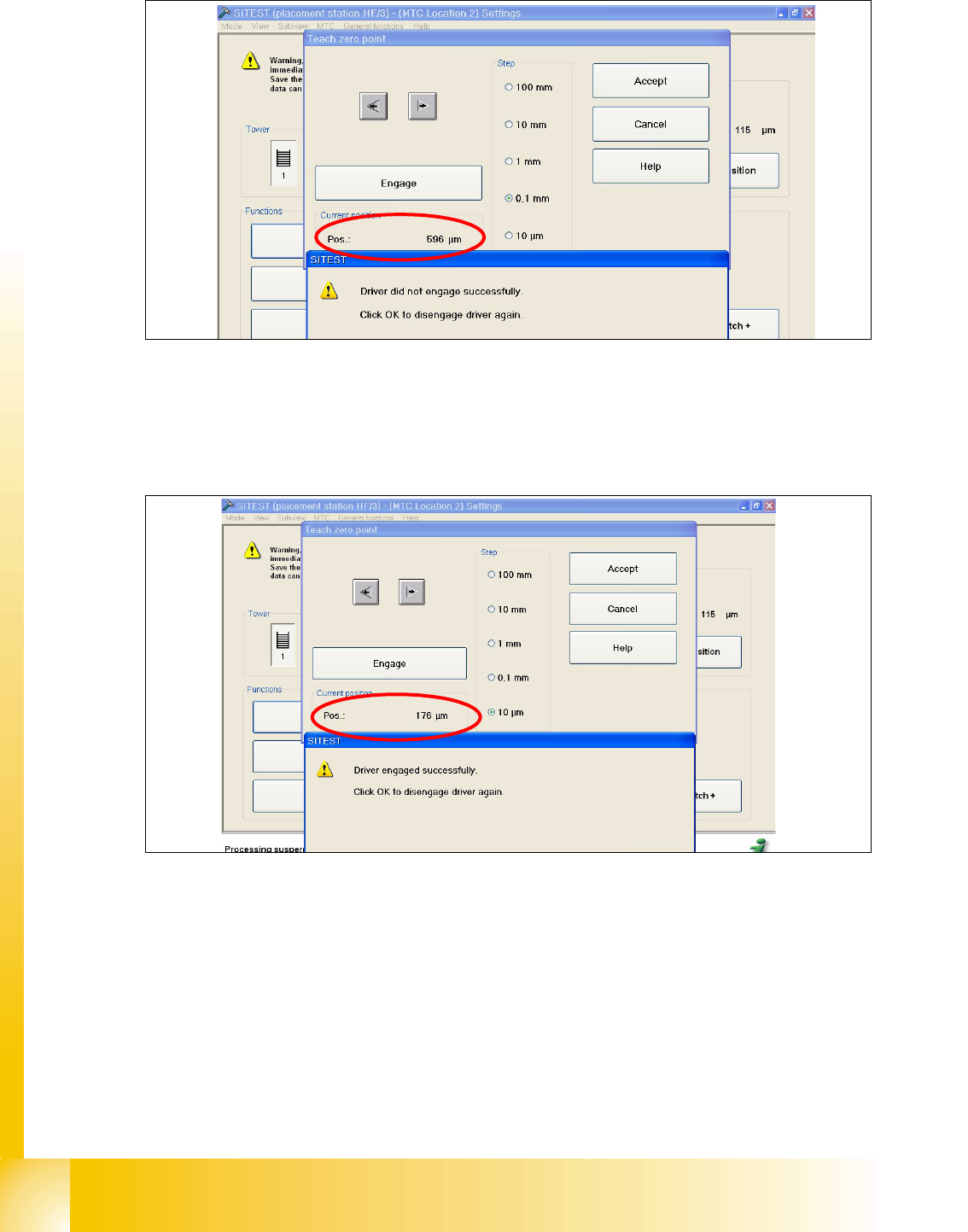
➠ Now calculate the middle position at which the driver will always engage.
e.g. |-257| + 596 = 853 divided 2 = 426µm
426 + the minimum pos. or maximum pos. - 426 = approx.169µm
Fig. 13.3 - 5 Correct position for the driver
➠ Check the driver position. The driver now should be correctly in the middle position of the notch
of the WTC.
➠ Press the button "ACCEPT"
➠ Check the position of the driver for the other cassettes.
1 - 41
Student Guide SIPLACE X
Edition 09/2005 13 MTC 2
41
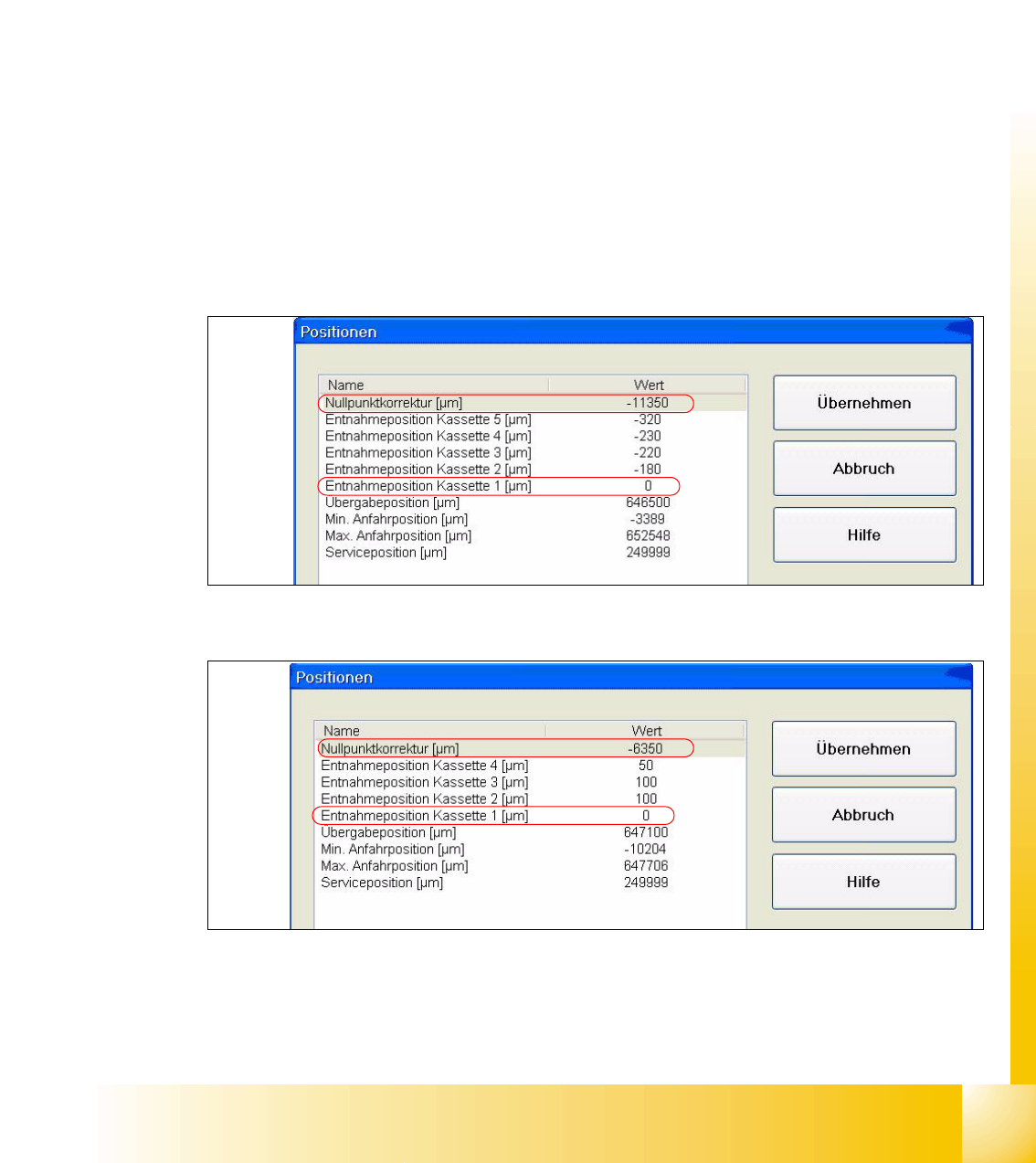
1b. Manuall Input of the Zero point correction 13
After the calibration of the zeropoint correction , the value will put in the row " removal position
Cassette 1" from the machine data.
Is this value to big, it is not possible to calibrate the max. and min. travel range of the feed axis.
Reason: The travel range will be calculate from the row "Zero point correction". When you have
the value zero in the row zero point correction, the feed axis move against the limit switch during
the calibration procedure.
Solution:
Put in the calibrated value in the row "Zero point correction" and the value zero in the row " Position
of removal Position cassette 1".
Sitest:
–MTC -->Axes
– Choose feed axis
– Press the button "Positions"
Fig. 13.3 - 6 Example: Input machine data tower 1
Fig. 13.3 - 7 Example: Input machine data tower 2
After the manuall Inputs, check the Zero point correction again.
1 - 42
Student Guide SIPLACE X
13 MTC 2 Edition 09/2005
42
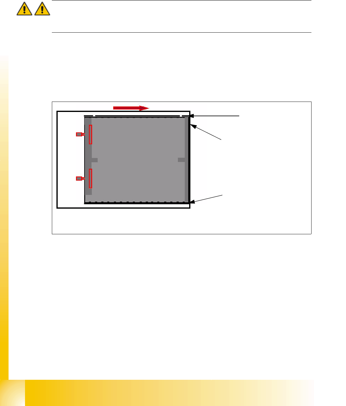
2a. Transfer position of the Tower 1 XL WTC 13
When you press the button to calibrate the Transfer position the tray moves approx. 5mm outside
of the feed axis.
Attention:
When you accept this calibration procedure with "ACCEPT" now, you get a wrong transfer position
and pick up position for the twin head.
➠ Open the cover and move the tray back in the direction to the lifting axes
➠ Then move the tray back in the direction to the machine and stop so that the plastic edge
comes into line with outer edge of the frame from the feed axis. You must do this in one step,
because that you eliminate the tolerance between the space and the driver and you don‘t need
a pick up offset for the tray.
Fig. 13.3 - 8 Transfer position XL tray
Plastic edge of the WTC
Edge of the frame from the MTC
Plastic edge of the WTC