SiplaceX4_en.pdf - 第61页
1 - 37 S tudent Guide SIPLACE X Edition 09/2005 2 Overview 37 2.2.10.5 Nozzle changer for 6 segment C&P head The nozzle chang er for a 6 segment C&P head cons ists of at least one, and up to twelve maga- zines, e…
1 - 36
Student Guide SIPLACE X
2 Overview Edition 09/2005
36
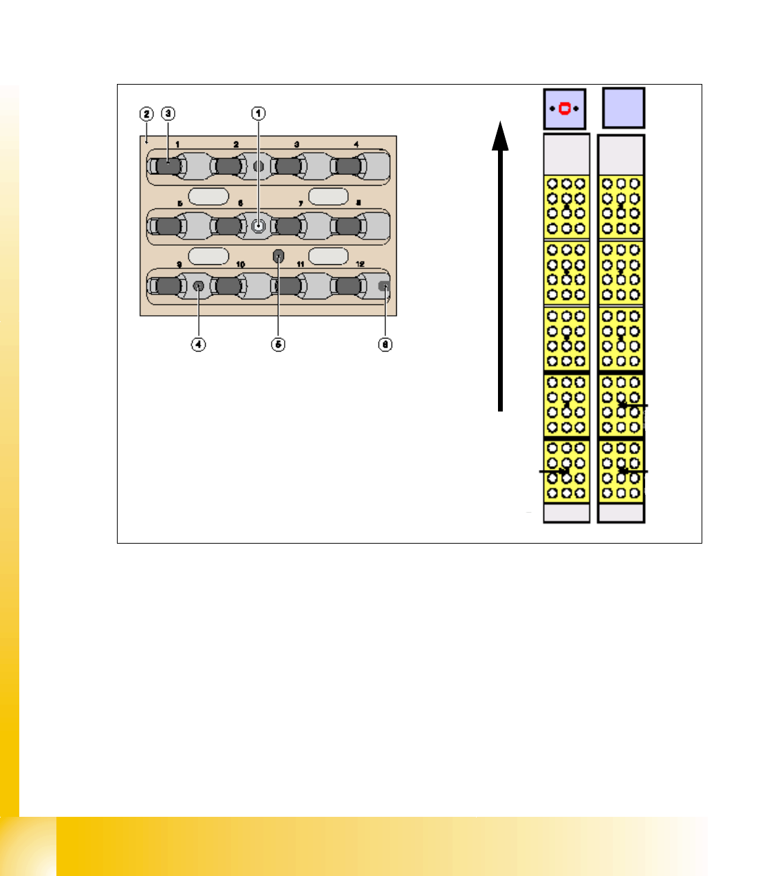
2.2.10.4 Nozzle changer for 12 segment C&P head
As an option on placement heads, a nozzle changer can be installed for each collect&place head.
This enables the nozzle configuration to be changed rapidly, thus allowing the collect&place head
to be quickly adapted to the needs of the placement process.
The nozzle changer consists of at least one, and up to ten magazines, each with twelve nozzle
garages (see Fig. 2.2 - 22). The magazines are seated on a common support and each magazine
is centered using two parallel pins and fixed in place with a spring hook.
Optionally, each garage can be configured with a different nozzle type.
Fig. 2.2 - 22 Nozzle changer and nozzle magazine for 12-segment C&P head
Key
(1) Calibration fiducial (2) Nozzle garage
(3) Locking plate (4) Hole for the parallel pin to center the
magazine
(5) Hole for the parallel pin to slide the locking
plate
(6) Slot for the parallel pin to center the mag-
azine
Magazin 6
Magazin 2
Magazin 1
Direction of trans-
port
1 - 37
Student Guide SIPLACE X
Edition 09/2005 2 Overview
37
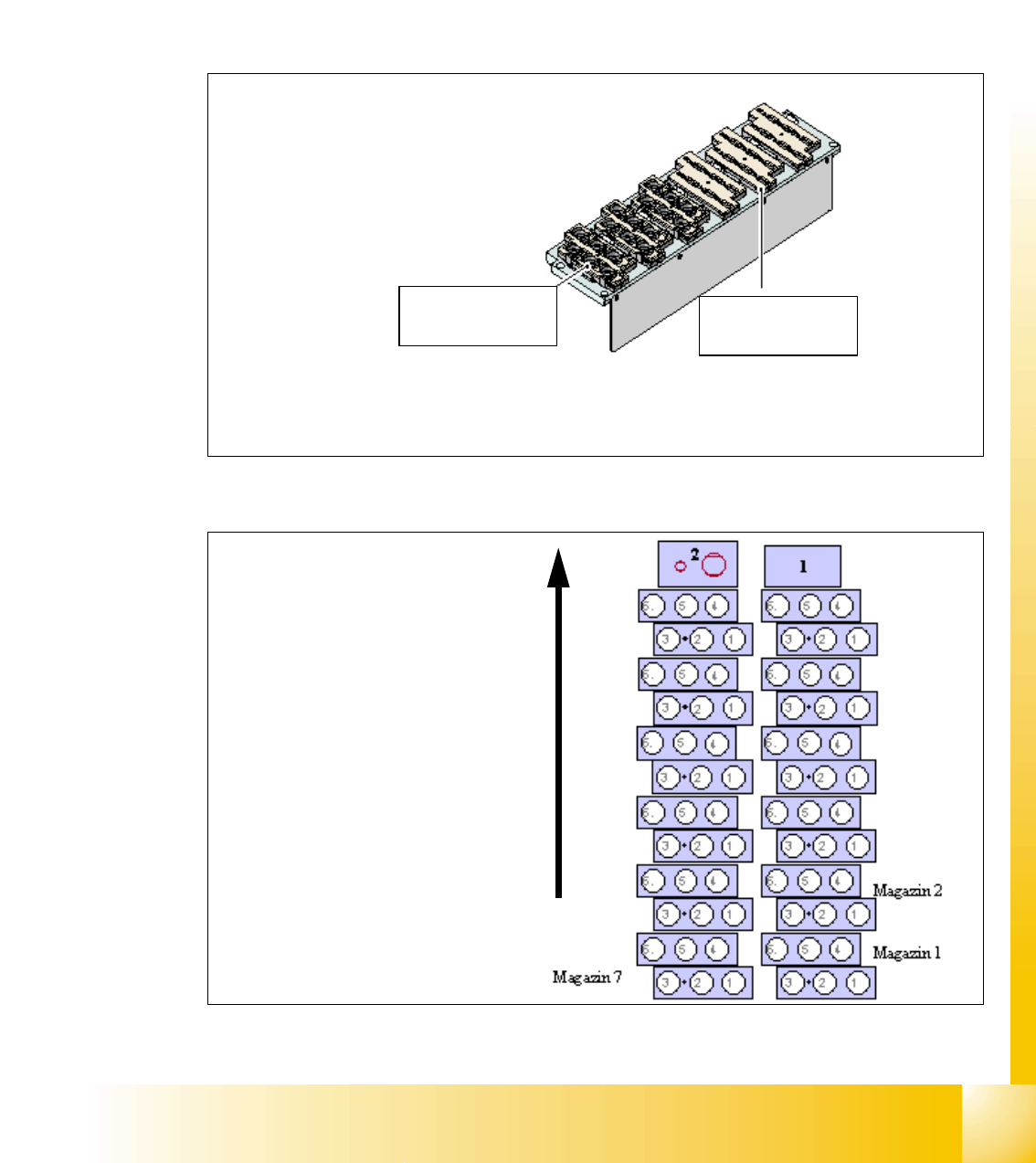
2.2.10.5 Nozzle changer for 6 segment C&P head
The nozzle changer for a 6 segment C&P head consists of at least one, and up to twelve maga-
zines, each with six nozzle garages (see Fig. 2.2 - 23). The magazines are seated on a common
support and each magazine is centered using two parallel pins and fixed in place with a spring
hook.
Magazines can be installed for the 9xx and 8xx nozzle types. These magazines can be arranged
as required.
Fig. 2.2 - 23 Nozzle changer 6-segment C&P head
Fig. 2.2 - 24
Magazin for 6
nozzle Typ 8xx
Magazin for 6
nozzle Typ 9xx
Direction of trans-
port
(1) Component reject position
(2) Nozzle reject position
1 - 38
Student Guide SIPLACE X
2 Overview Edition 09/2005
38
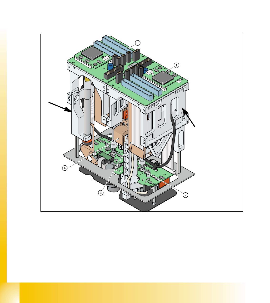
2.2.11 Twin Head
2.2.11.1 Description
The twin head consists of two identical P&P heads which work according to the pick&place prin-
ciple.The second P&P head is mounted on the gantry at an angle of 180 degrees. Two compo-
nents (one from each P&P head) can be picked up in succession from the feeder module and
optically centered with the help of the camera. On the way to the placement position, the compo-
nents are rotated into the correct position. They are then carefully and precisely positioned onto
the PCB with the help of controlled air kiss and a predefined force.
Type 5xx nozzles are used for the twin head. Type 4xx nozzles from the pick&place head and type
8xx and 9xx nozzles from the collect&place heads can be used with an adapter.
Fig. 2.2 - 25 Twin head
1. Main board on respective module (1 or 2)
2. D-axis
3. Z-axis linear motor
4. Z-axis incremental measurement system
Module 2, at an angle o
f
180 °
to module 1.
Module1