SiplaceX4_en.pdf - 第615页
1 - 48 S tudent Guide SIPLACE X 13 MTC 2 Edition 09/2005 48 13.3.3.1 Belt tension Note: The construction of the lif ting axis was change si nce 05.2005. That means new spindle, spindle with counter be aring, motor liftin…
1 - 47
Student Guide SIPLACE X
Edition 09/2005 13 MTC 2
47
13.3.3 Adjustments Lifting Axes
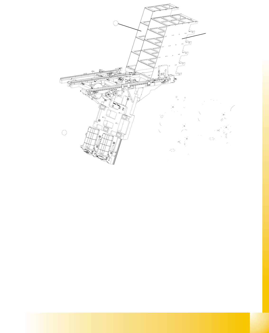
Fig. 13.3 - 13 Overview of the lifting axes
Key
1 Lifting axis tower 1
2 Lifting axis tower 2
3 Servo motors of the lifting axes
4 Dual toothed belt (shown here for tower 2)
5 Spindle (shown here for tower 2)
6 Inductive sensors (shown here for tower 2)
7 Holes for the measurement head of the belt frequency measuring device
3
2
1 - 48
Student Guide SIPLACE X
13 MTC 2 Edition 09/2005
48
13.3.3.1 Belt tension
Note:
The construction of the lifting axis was change since 05.2005. That means new spindle, spindle
with counter bearing, motor lifting axis, gear on the motor and therefore new parametersets for
Masterdrives. The MTC 2 has the versionsnumber 02. The belt tension for the lifting axis was
change, please note!
Tools and accessories 13
– Belt frequency measurement device (inductive)
– 2 belt tension stickers
– 1 set of hexagon socket wrenches
– 1 set of open-ended wrenches
Preparatory measures 13
➠ Empty the MTC 2 completely (see the User Manual).
➠ Move the lifting axis to its lowest position (see Sitest ).
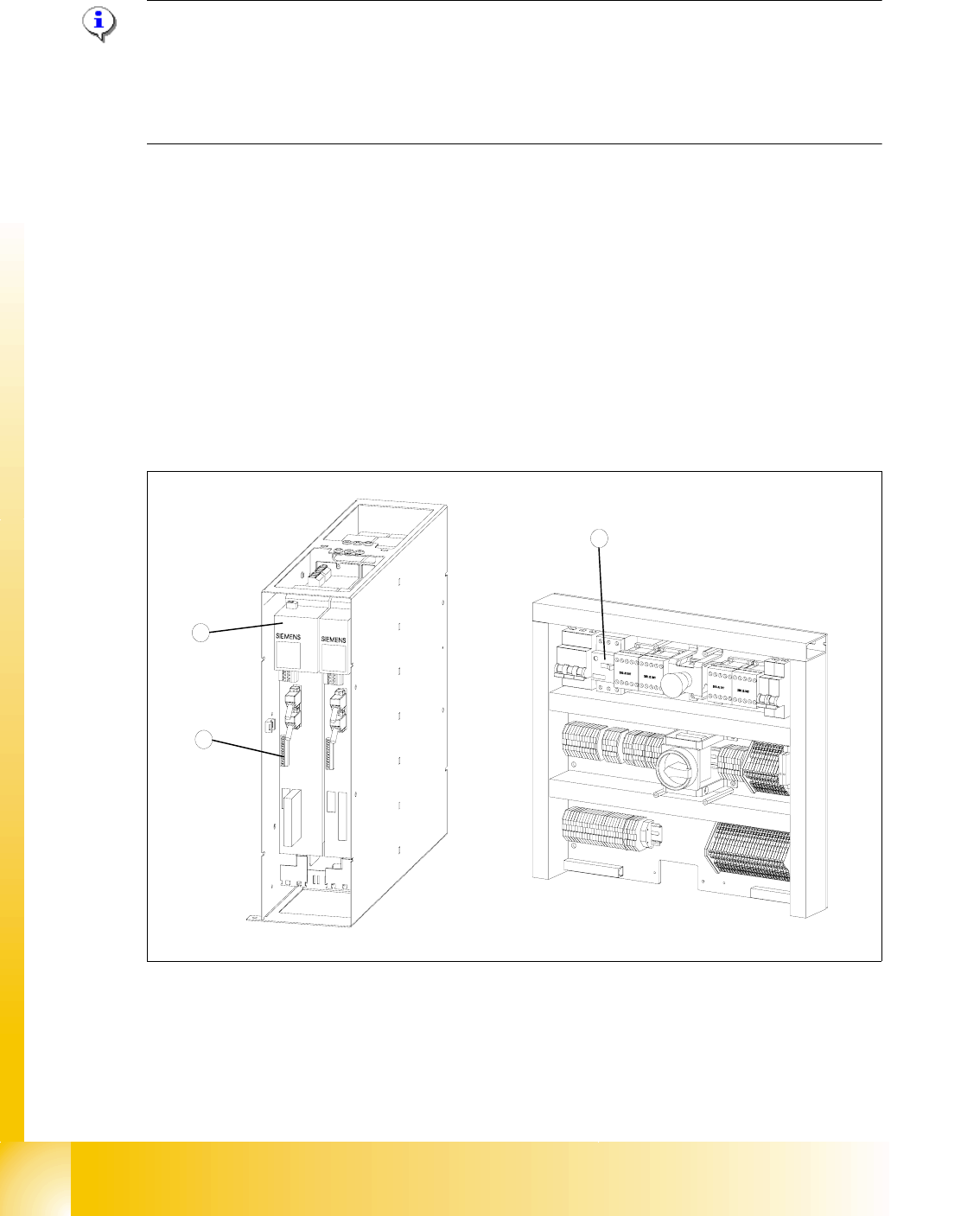
Fig. 13.3 - 14 Connections to the Masterdrives of the lifting axes
Key
1 Masterdrive, lifting axis (shown here for tower 1)
2 Connection terminal for external signals
3 Motor protection switch on the electronics board
2
1
3

1 - 49
Student Guide SIPLACE X
Edition 09/2005 13 MTC 2
49
➠ Remove the left cover in front of the electronics board and the covers on the right and the left
in front of the Masterdrives.
➠ Switch the motor protection switch off (see Fig. 13.3 - 14).
➠ To relieve the tension the toothed belts, loosen the brake on the servo motor in the following
way to rest the lifting axis on the buffer:
➠ Check that the MTC 2 has been switched off and is isolated from the power supply.
➠ Remove the connector for external signals from the Masterdrive for the lifting axis (see Fig.
13.3 - 14
, item 2).
➠ Move the cable from Pin 3 to Pin 1.
➠ Attach the connector.
➠ Connect the MTC 2 to the power supply and switch it on.
The lifting axis audibly moves a distance of a few mm up to the buffer.
➠ Check that the lifting axis is actually at its end position.
➠ Reconnect the cable as it was originally in the following way:
➠ Switch off the MTC 2 and isolate it from the power supply.
➠ Remove the connector for external signals from the Masterdrive for the lifting axis (see Fig.
13.3 - 14
, item 2).
➠ Move the cable from Pin 1 to Pin 3.
➠ Attach the connector.
➠ Switch the motor protection switch on.
➠ Attach the covers.
➠ Undock the MTC 2 from the SIPLACE station (see User Manual).
➠ Crank up the MTC 2 in a clockwise direction until it stops.