SiplaceX4_en.pdf - 第628页
1 - 61 S tudent Guide SIPLACE X Edition 09/2005 13 MTC 2 61 13.3.4.4 Checking and setting the WTC safet y queries NOTE The WTC safety queries each comprise a light barrier which is interrupte d by the front edge of the W…

1 - 60
Student Guide SIPLACE X
13 MTC 2 Edition 09/2005
60
Checking and setting the handle sensors 13
NOTE
The handle sensors each comprise a reflecting light barrier which can detect the handle of the
WTC or the side of the handle of the WTC XL. An LED indicates the switching status of the sensor.
Fig. 13.3 - 23 Checking and setting the handle sensors
Key
1 Reflecting light barriers of the handle sensors
2 Mounting plates with clamping screws
3LEDs
➠ Unscrew the clamping screws of the mounting plate.
➠ Move the mounting plate in the direction of the WTC until the reflecting light barrier responds
(the LED will change its status). Fix the plate in place there.
➠ Ensure that the status of the LED remains the same when you move the locked WTC. If
necessary, move the mounting plate a little further in the direction of the WTC.
➠ Firmly tighten the clamping screws.
3
2
1
1 - 61
Student Guide SIPLACE X
Edition 09/2005 13 MTC 2
61
13.3.4.4 Checking and setting the WTC safety queries
NOTE
The WTC safety queries each comprise a light barrier which is interrupted by the front edge of the
WTC or the WTC XL. Two LEDs indicate the switching status of the sensor.
NOTE
Make the settings for the feed axis of tower 1 first and then the feed axis of tower 2.
The light barrier holder in the middle accepts the light barriers for both axes but cannot be set
separately. When making settings, both the holder for the sender and the holder for the receiver
of the light barrier pairs must be moved.
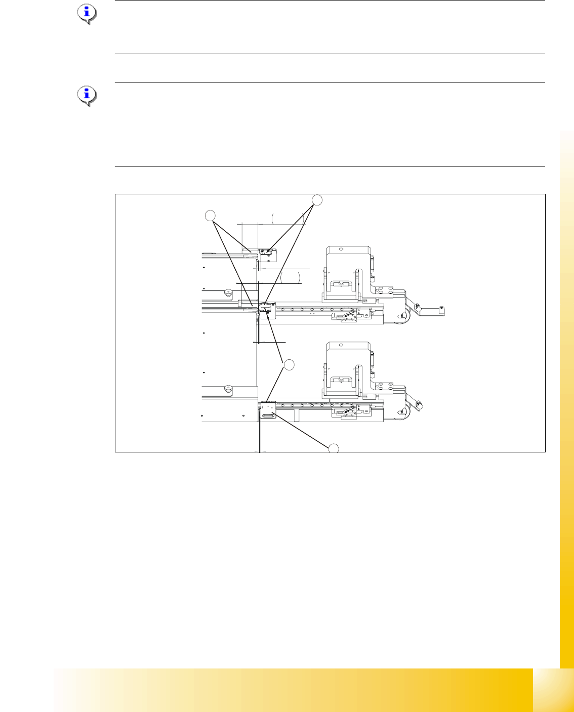
Fig. 13.3 - 24 Checking and setting the WTC safety query
Key
1 Light barrier for the WTC safety query for tower 1
2 Light barrier for the WTC safety query for tower 2
3 Light barrier holder with clamping screws
➠ Unscrew the clamping screws on the middle holder and move it by the following fixed adjust-
ment amounts (see
Fig. 13.3 - 24Checking and setting the WTC safety query):
-Tower 1, left side = 3 mm
-Tower 1, right side = 4 mm
-Tower 2, left side = 4 mm
-Tower 2, right side = 5.5 mm
1
2
3
32,50
34
4
5,50
3
3
1 - 62
Student Guide SIPLACE X
13 MTC 2 Edition 09/2005
62
➠ Ensure that the status of the LEDs remains the same when you move the locked WTCs. If
necessary, move the holders a little further away from the front edge of the WTCs.
➠ Firmly tighten all clamping screws and varnish them when they have been set.
NOTE
The following must be observed for a functional test on the light barrier setting:
- Light barriers must not respond when the lifting axes are moved. When a preliminary setting has
been made, the lifting axis must therefore be moved in 0.1 mm steps over a distance
corresponding to the height of a WTC next to the light barrier to test the setting.
- If the light barrier responds, the emergency stop function is triggered. The emergency stop
status can only be reset, however, when the receiver receives a signal from the transmitter
again.
Loosen the clamping screws on the light barrier holder (transmitter and receiver). Move them
both in the direction of the feed track (away from the tower) until the receiver’s status indicator
switches from red to green. When moving the lifting axis, ensure that the front edge of the WTC
is positioned within the capture area (chamfer) of the adjustment gauge Checking and setting
the crash light barriers.
Check and adjustment the crash light barriers 13
NOTE
The crash light barriers each comprise a light barrier which is activated by a waffle pack tray of a
specific height and is interrupted by a protruding component. Two LEDs indicate the switching
NOTE
Make the settings for the feed axis of tower 1 first and then the feed axis of tower 2.
The light barrier holder in the middle accepts the light barriers for both axes but can be set sepa-
rately (it comprises a base section and a movable section). When making settings, both the holder
for the sender and the holder for the receiver of the light barrier pairs must be moved.
➠ Place the adjustment gauge for the crash light barriers XL across onto the rail of the feed
axis for tower 1.
➠ Unscrew the clamping screws of the holder for tower 1 and the middle holder (base section)
and place the bottom light barrier pair onto the middle of the gauge. Ensure that the holders do
not jam in their guide.
➠ Firmly tighten the clamping screws. Ensure that the holders cannot be moved or turned any
more.
➠ At this setting, the bottom light barrier pair should still just shine through at a height of
12.35 mm + 0.05 mm and no longer shine through at a height of 12.45 mm + 0.05 mm.(size in
the technical documentation)