SiplaceX4_en.pdf - 第64页
1 - 40 S tudent Guide SIPLACE X 2 Overview Edition 09/2005 40 2.2.12 C&P20 Head C&P20 head Key: 2 T echnical data 2 2 St a r m o t o r 8 Component camera (1) S tar with 20 segment s (DP drives) (2) "V acuum …
1 - 39
Student Guide SIPLACE X
Edition 09/2005 2 Overview
39
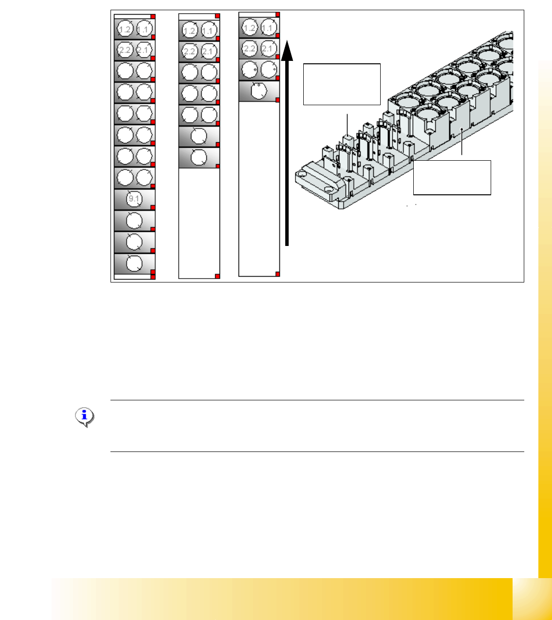
2.2.11.2 Nozzle Changer for Twin Head
Siplace X machines with twin heads are always equipped with a nozzle changer, which is installed
in sector 3 or 1.
The nozzle changer for a twin head consists of the standard module with 3 garages, each with two
nozzles and one garage for a special nozzle (see Fig. 2.2 - 26).
Fig. 2.2 - 26 Nozzle changer for twin head
1. Standard nozzle changer
2. Extended nozzle changer
3. Complete nozzle changer
Note:
The configurations mentioned above can be changed as required and individual magazines for
standard and special nozzles can be added.
Magazin for 1
special nozzle
Magazin for 2
standard nozzle
Direction of trans-
port
1 - 40
Student Guide SIPLACE X
2 Overview Edition 09/2005
40
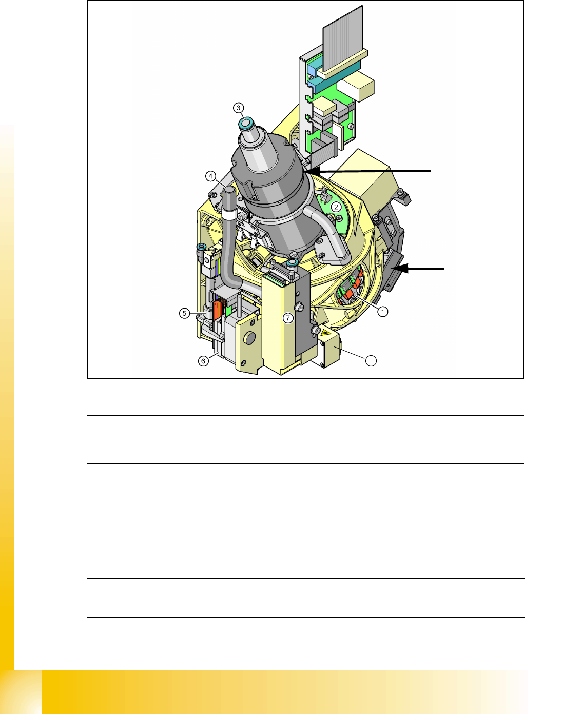
2.2.12 C&P20 Head
C&P20 head Key: 2
Technical data 2
2
Star motor
8
Component
camera
(1) Star with 20 segments (DP drives) (2) "Vacuum sensor for hold circuit board
(3) Compressed air supply for hold, pickup
and placement circuits
(4) X-linear motor cooling system
(discharged air from pressure control valve
(5) Return cylinder for Z-axis (6) Z-linear motor with measurement system
(7) Pressure control valve for pickup and
placement circuits
(8) Component sensor
Components 0402 to 2220, Melf, SOT, SOD
Maximum component size 6mm x 6mm x 4mm L/W/H
Minimum component size 0.2mmx 0.2mm
Maximum component weight 1g

1 - 41
Student Guide SIPLACE X
Edition 09/2005 2 Overview
41
2.2.12.1 Description
The 20-segment collect&place head functions according to the collect&place principle i.e.
twenty components are picked up from the feeder module (X-feeder only) during any one cycle.
The component sensor checks the placement/pickup positions to determine whether a component
has been picked up by the nozzle or whether the component has been placed. On the way to the
placement position, the components are rotated and optically centered. Before placement is per-
formed, the Vision system determines the angle and X/Y position correction factor. The X/Y posi-
tion correction factor is included in the calculation of the placement position. The ability of each
segment to rotate independently from the star enables angle correction to be performed sepa-
rately for each segment. The components are then positioned accurately on the PCB, with the
help of controlled air kiss.
The component camera is still integrated into the C&P20 head. This saves unnecessary travel
to the external centering cameras.
Each segment has its own DP drive for correct rotation of components. The segments are there-
fore no longer rotated together into the correct angle position on a single star but can be indepen-
dently turned.
Each segment has its own vacuum generator.
The Z-drive for the segments has been realized with a linear motor and linear position measuring
system for optimum precision. In the pickup/placement position, the Z-drive moves the segments
vertically (upwards and downwards).