SiplaceX4_en.pdf - 第642页
1 - 72 S tudent Guide SIPLACE X 13 MTC 2 Edition 09/2005 72 13.4.2 Import ant Parameter for trouble shooting – U / r = visualization parameters – P = parameters which can be ch anged – r004 = Output current inverter , co…
1 - 71
Student Guide SIPLACE X
Edition 09/2005 13 MTC 2
71
13.4 Masterdrives
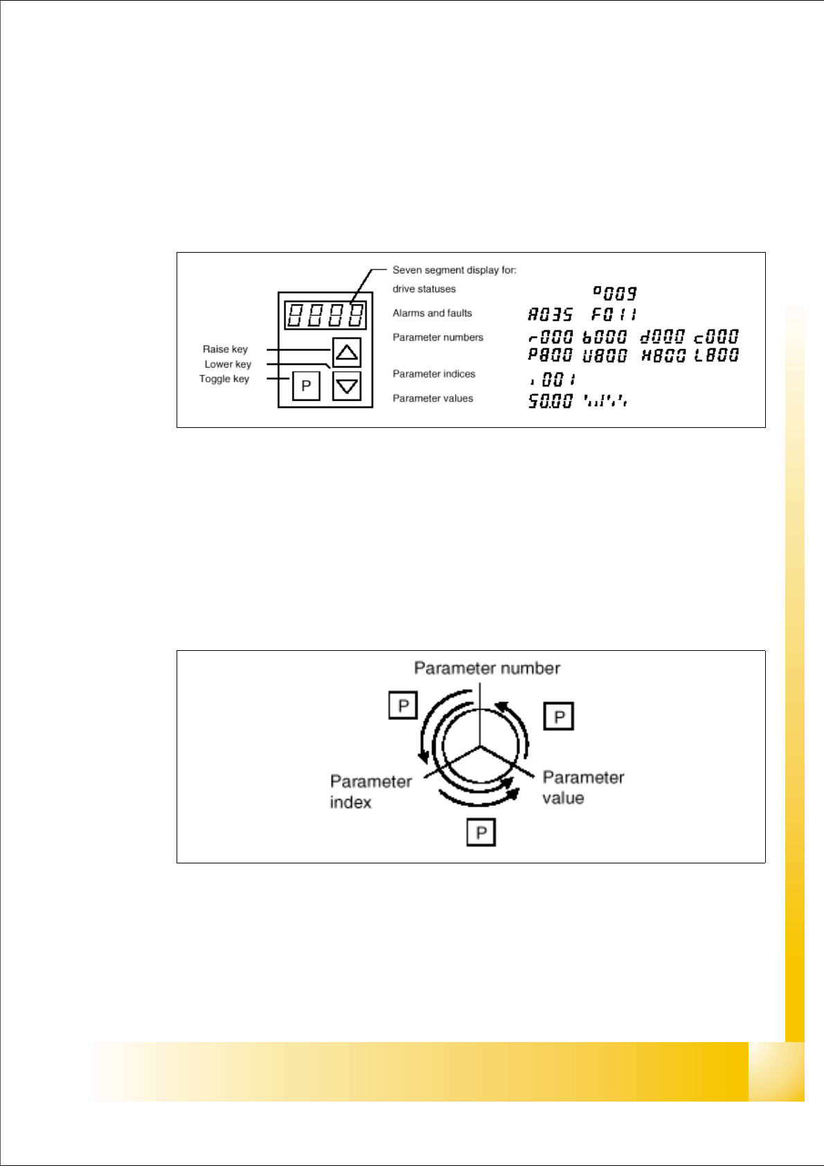
13.4.1 Operating the master drive with the parametrization unit (PMU)
The PMU parameterizing unit enables parameterization, operator control and visualization of the
converters and inverters directly on the unit itself.
Fig. 13.4 - 1 PMU parameterizing unit
With the toggle key, you can change over:
– from the parameter number to the parameter index
– from the parameter index to the parameter value
– from the parameter value to the parameter number
If the parameter is not indexed, you can jump directly from the parameter number to the parameter
value.
Fig. 13.4 - 2 Toggle key of the PMU

1 - 72
Student Guide SIPLACE X
13 MTC 2 Edition 09/2005
72
13.4.2 Important Parameter for trouble shooting
– U / r = visualization parameters
– P = parameters which can be changed
– r004 = Output current inverter, converter
– r006 = actually DC link voltage
– r009 = Temperature motor
– r069 = Software version Index 1 main unit
Index 2 Option unit slot A
13
Index 3 Option unit slot B 13
Index 4 Option unit slot C 13
– U003 = Parameter set version:
for the Feed axis tower 1/2 software version
for the Lifting axis tower 1/2 software version
Note:
On the MTC 2 are four different parameter sets, because the mechanical construction for tower 1
and tower 2 is different.
– U501 = Machine data
– P060 = Function parameter to choose actually menu.
Index 4:Unit configuration: Address
13
– P095 = Motor list with standard motors
– P096 =Function parameter motor
Define serial Interface: 13
– P700 interface address of COM 1
– P701 baud rate 8 is equal to 38400

1 - 73
Student Guide SIPLACE X
Edition 09/2005 13 MTC 2
73
13.4.3 Factory settings
Reset the Master drives to the define defaults
NOTE
When setting factory defaults, the axis concerned must not be subject to position control.
You must change 3 Parameters to define the defaults after this you can download the parameter
set for the axis.
1. Change Parameter P053 from 7 to 6 (This value is a Binary code 0111
→ 0110).
2. Set Parameter P060 from 7 to 2.
3. Change Parameter P970 from 1 to 0. Parameter-Reset is started.
Check the serial interface and CAN Bus address after RESET: 13
1. Adjust the V24 (RS232) Interface.
Parameter P700 = 0
Parameter P701
→ Index 1= 8 (8 = Baud rate 38400).
2. Check the address for Can -Bus Parameter P918.
3. Download the Parameter set for the Axis with the Laptop.