SiplaceX4_en.pdf - 第643页
1 - 73 S tudent Guide SIPLACE X Edition 09/2005 13 MTC 2 73 13.4.3 Factory settings Reset the Master drives to the define default s NOTE When setting factory default s, the axis concerned must not be subject to position …

1 - 72
Student Guide SIPLACE X
13 MTC 2 Edition 09/2005
72
13.4.2 Important Parameter for trouble shooting
– U / r = visualization parameters
– P = parameters which can be changed
– r004 = Output current inverter, converter
– r006 = actually DC link voltage
– r009 = Temperature motor
– r069 = Software version Index 1 main unit
Index 2 Option unit slot A
13
Index 3 Option unit slot B 13
Index 4 Option unit slot C 13
– U003 = Parameter set version:
for the Feed axis tower 1/2 software version
for the Lifting axis tower 1/2 software version
Note:
On the MTC 2 are four different parameter sets, because the mechanical construction for tower 1
and tower 2 is different.
– U501 = Machine data
– P060 = Function parameter to choose actually menu.
Index 4:Unit configuration: Address
13
– P095 = Motor list with standard motors
– P096 =Function parameter motor
Define serial Interface: 13
– P700 interface address of COM 1
– P701 baud rate 8 is equal to 38400

1 - 73
Student Guide SIPLACE X
Edition 09/2005 13 MTC 2
73
13.4.3 Factory settings
Reset the Master drives to the define defaults
NOTE
When setting factory defaults, the axis concerned must not be subject to position control.
You must change 3 Parameters to define the defaults after this you can download the parameter
set for the axis.
1. Change Parameter P053 from 7 to 6 (This value is a Binary code 0111
→ 0110).
2. Set Parameter P060 from 7 to 2.
3. Change Parameter P970 from 1 to 0. Parameter-Reset is started.
Check the serial interface and CAN Bus address after RESET: 13
1. Adjust the V24 (RS232) Interface.
Parameter P700 = 0
Parameter P701
→ Index 1= 8 (8 = Baud rate 38400).
2. Check the address for Can -Bus Parameter P918.
3. Download the Parameter set for the Axis with the Laptop.
1 - 74
Student Guide SIPLACE X
13 MTC 2 Edition 09/2005
74
13.4.4 Setting the CAN bus address at the master drive PMU
It is necessary to enter the addresses of the feed and lifting axes on the PMU’s (Parameterization
Units) for the Master drives on initial commissioning of the MTC and after the replacement of the
Master drives. This can be performed external to the MTC. The Master drives must be supplied
with 24 V DC. The control for the related axis must be shut down.
Note:
For setting the CAN Bus address you could use the software "Drive Monitor". When you adjust
the CAN Bus address manually please use the instruction in chapter 13.3.
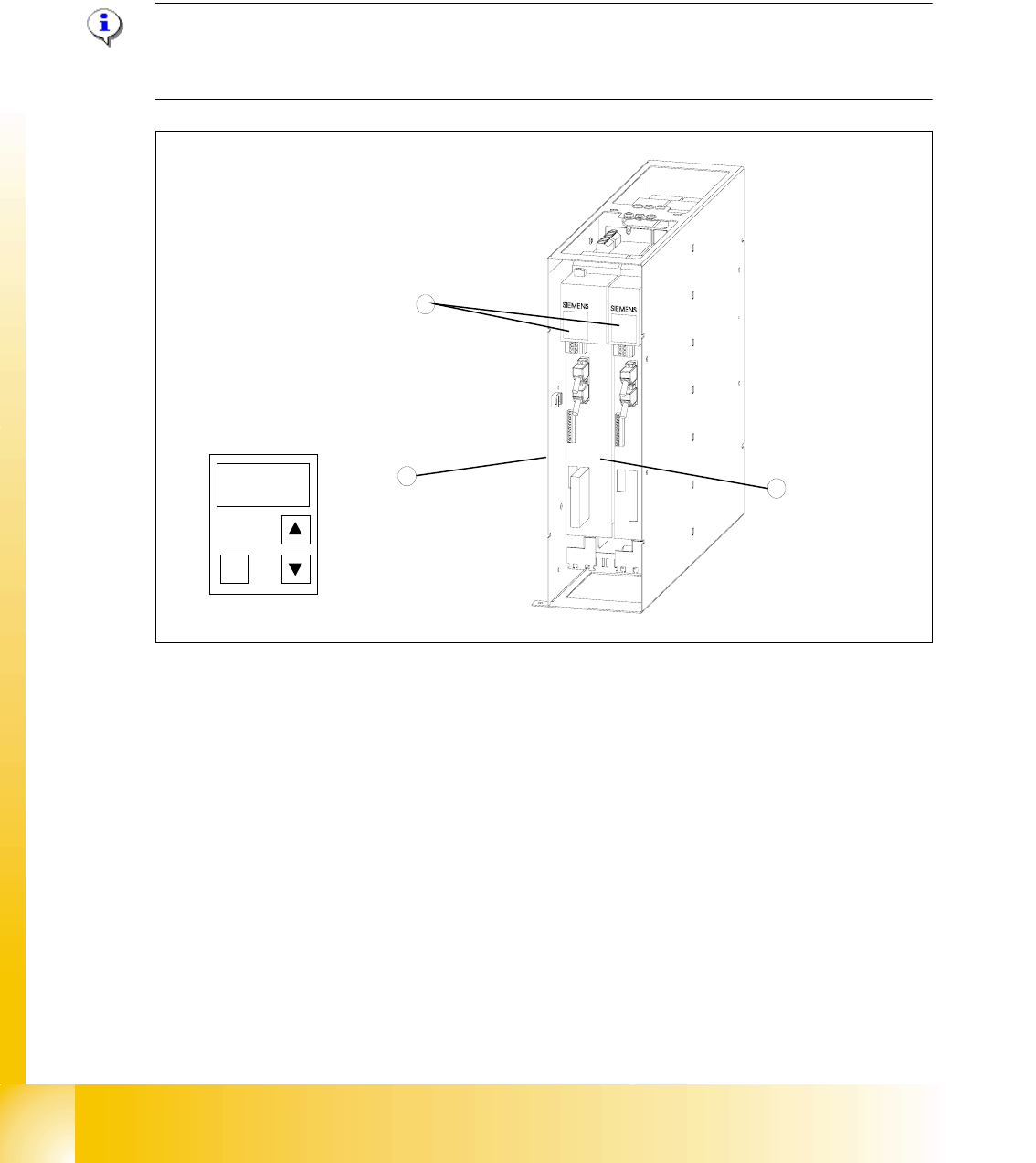
Fig. 13.4 - 3 Masterdrives of the lifting and feed axes (shown here for tower 1)
Key
1 Masterdrive of the lifting axis for tower 1
2 Masterdrive of the feed axis for tower 1
3 Control panels
These brief instructions show how to enter the address for the Masterdrive of the lifting axis for
tower 1. The procedure is similar for the other axes (but with different addresses). For more
detailed information, see the chapter "Parameterization" in the user manual for "SIMOVERT
MASTERDRIVES".
1
2
3
P