SiplaceX4_en.pdf - 第645页
1 - 75 S tudent Guide SIPLACE X Edition 09/2005 13 MTC 2 75 The following addresses are pr ovided for the lifting and feed axes: T able 13.4 - 1 Addresses of the Masterdrives 1 Press , to go to the parame ter numbers. 2 …
1 - 74
Student Guide SIPLACE X
13 MTC 2 Edition 09/2005
74
13.4.4 Setting the CAN bus address at the master drive PMU
It is necessary to enter the addresses of the feed and lifting axes on the PMU’s (Parameterization
Units) for the Master drives on initial commissioning of the MTC and after the replacement of the
Master drives. This can be performed external to the MTC. The Master drives must be supplied
with 24 V DC. The control for the related axis must be shut down.
Note:
For setting the CAN Bus address you could use the software "Drive Monitor". When you adjust
the CAN Bus address manually please use the instruction in chapter 13.3.
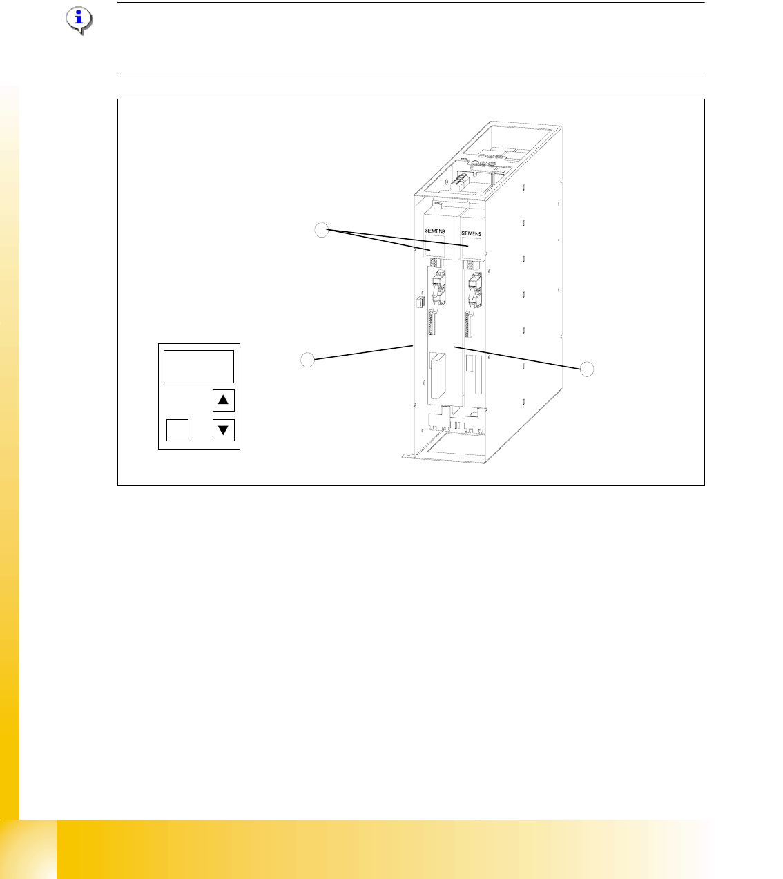
Fig. 13.4 - 3 Masterdrives of the lifting and feed axes (shown here for tower 1)
Key
1 Masterdrive of the lifting axis for tower 1
2 Masterdrive of the feed axis for tower 1
3 Control panels
These brief instructions show how to enter the address for the Masterdrive of the lifting axis for
tower 1. The procedure is similar for the other axes (but with different addresses). For more
detailed information, see the chapter "Parameterization" in the user manual for "SIMOVERT
MASTERDRIVES".
1
2
3
P
1 - 75
Student Guide SIPLACE X
Edition 09/2005 13 MTC 2
75
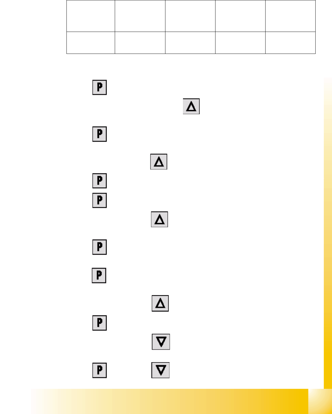
The following addresses are provided for the lifting and feed axes:
Table 13.4 - 1 Addresses of the Masterdrives
1 Press , to go to the parameter numbers.
2 Step through the parameter numbers with , until "P060" appears on the seven segment
display. This is the menu selection.
3 Press . A number appears on the display. This is the "Parameter menu" menu
command.
4 Step through the options with , until "
4" is displayed. ("4" means "Module configuration").
5Press . "
004" is displayed. This is the status indicator for "Module configuration".
6 Press to go to the parameter numbers. "
P060" is displayed.
7 Step through the options with until "
P918" appears on the seven segment display. This
is the parameter number for the bus address.
8 Press to go to the parameter index. "
001" indicates that this is Index 1 (an index is
always indicated by a small line).
9 Press to go to the parameter value. "
1" is displayed. This is the address of the lifting axis
for tower 1.
10 Set the relevant address with (see
Table 13.4 - 1).
11 Press to return to the parameter numbers. "
P918" is displayed again.
12 Step through the options with until "
P060" appears. Now you are back in the menu
selection.
13 Press and set "
1" with . This returns you to the menu command "Parameter
Lifting axis
Tower 1
Feed axis
Tower 1
Lifting axis
Tower 2
Feed axis
Tower 2
Address
1234