SiplaceX4_en.pdf - 第659页
Edition 09/2005 SIPLACE X Appendix 4 20 Fig. 20.2 - 1 Flow diagram of SIPLACE Axis T ester V e rsion 1.5 in Expert mode <- | TE Samples 511, Time 0,5ms , Axis X, Scale 3/4.3, Scope 15/-10, Range 4 0 ms, Pull off: 2,00…

SIPLACE X Edition 09/2005
Appendix
3
20 Appendix
20.1 Using the SIPLACE Axis Tester ’SAT’
20.1.1 General Information
The SIPLACE Axis Tester has an integrated screen saver. If the program is not used for several
minutes (15) the screen saver will activate and show an increasing number of "stars". (The posi-
tion deviation signal at the BNC output will be switched to ’0’). As soon as the operator presses
any key, ’SAT’ will reactivate and display the menu last used.
The cursor is moved by "scrolling" in a particular direction. This means, that when the cursor is in
the topmost position of ’Cursor UP’, the bottommost menu will be selected and when it is moved
to the far left of the screen with ’Cursor LEFT’, the menu on the right will be chosen and vice versa.
20.1.1.1 Programming Buttons and Functions During SAT Booting
During booting, the ’SAT’ performs a so-called self-test i.e. the device tests itself and the internal
voltage values in the axis controller module. If the deviation is 5% (standard setting) or more, a
warning will be issued. The following settings can be modified during booting.
SAT’ ’Restart
Press B1 B3 and B5 simultaneously
’SAT’ will be reset/rebooted.
Return to Expert mode
Select ’User
level’ and ’Expert’ mode after confirming
the selection the system reboot in the
selected mode.
Fig. 20.1 - 1’SAT’ operating menu during system
boot
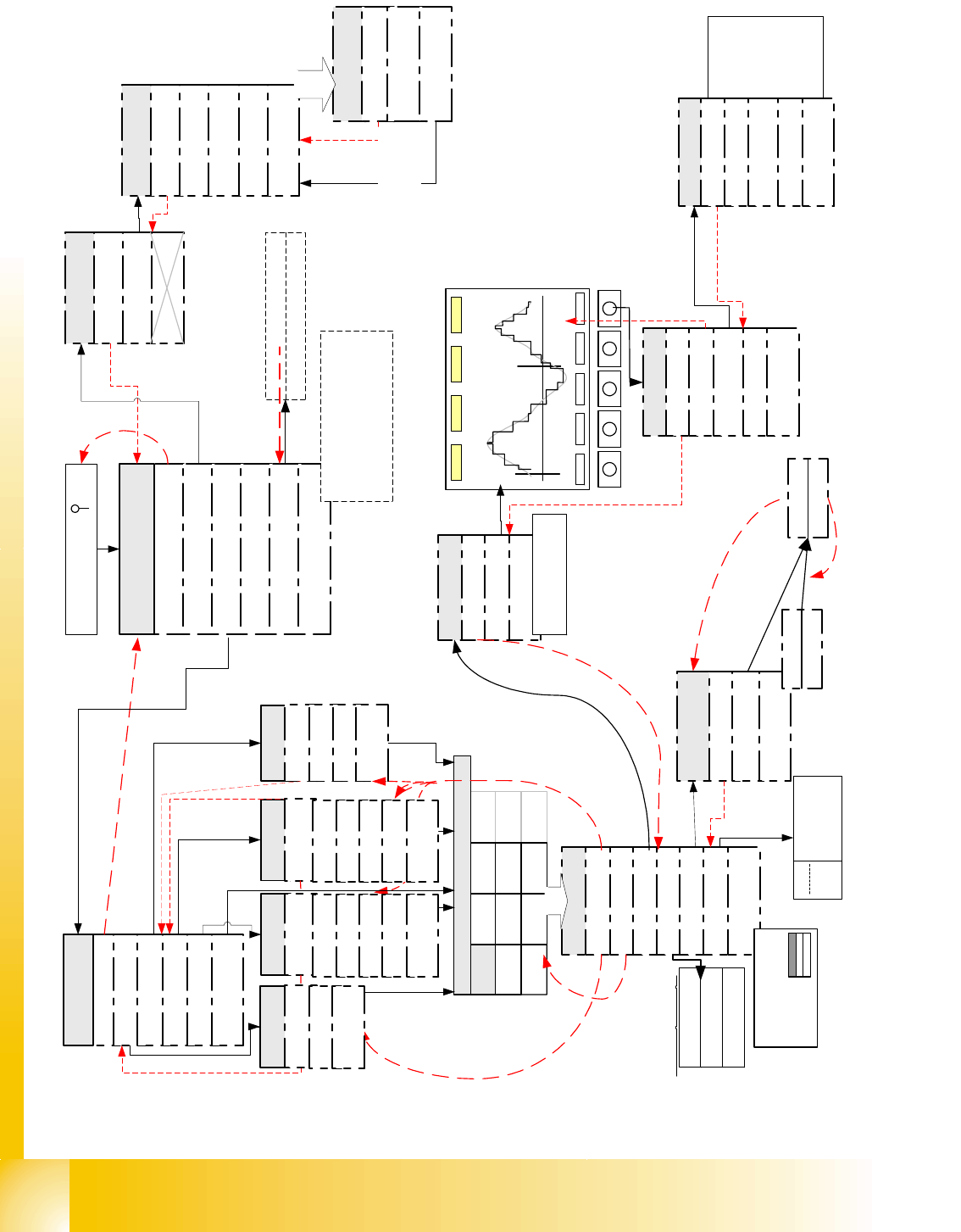
20.2 Flow Diagrams for Key ’SAT’ Menus
The following page shows an overview Fig. 20.2 - 1 - in Expert mode - of the configuration menus
required for track signal test, axis dynamics tests and adjustment. Each menu will then be ex-
plained in detail.
B1 B2 B3 B4 B5
Edition 09/2005 SIPLACE X
Appendix
4
20
Fig. 20.2 - 1 Flow diagram of SIPLACE Axis Tester Version 1.5 in Expert mode
<-
|
TE
Samples 511, Time 0,5ms, Axis X,
Scale 3/4.3, Scope 15/-10, Range 40 ms,
Pull off: 2,001ms Ctrl.: 51.589ms
Pos.: 53,590ms Overshoot 2
X
Y
Z
DP
NC
Z
DP
NC
Z
IC
NC
D
IC
*
Board: 1, Axis X, Addr: 0
Top axis controll. M1
Middle axis cont. M2
Bottom axis cont. M3
Dynamic signals of
Boot and press ' '
Quit
Configuration
Machine
System control
Shutdown
About ...
Main menu
Compilation: Jul 04 2003
Serial number: 1234567
FPGA Version: 1.0
Free memory
Back
YES
Properties
Back
Select Axis
Pos. quality
Adjust panel
Track signals
Serial connect
Machine Info
Back
Track signals
Reference error
Line error
Usage see detail
description
Show all
Time > 5 ms
Quit
Back
<
_
|
f
.
m
e
a
s
m
.
<
_
|
f
.
m
e
a
s
u
r
m
e
n
t
Pos. quality
Back
Positioning time
Overspeed
Start the measure-
ment with <
_|
Proceeding
Quit
Back
Oscilloscope Mode
Start FFT
Start Plot
Proceeding
Back
Line 1
Line 2
Line 3
Line 4
Start the
Measurement
... with <
_|
Stop ... with
<
_|
..of
Pos.deviation
signal
Configuration
Back
Panel
Config Unit
Panel
Back
Selection 1
Selection 2
Selection 3
Selection 4
outputs for pos.qualit
y
output for Track signa
l
outputs for comparisio
n
act.pos. to end sig.
output
for internal signa
Panel
Back
Change Panel (single
Line)
Activate Panel
<
_|
727866 Axis is referenced
FW enabled servo
.....
F5 HM
CAN speed 1 MHz
Current axis
-> number of
axis controller
cards
Only now the desired
outputs are connected
to BNC
choose F-
machine
Back
C-Serie
SIPLACE HF
F Machine
S Machine
HS Machines
Choose Machine
choose C-
machine
Back
Back
F3
F4
F5
F5 HM
WPC
choose S-
machine
Back
G
S15
S20
S23/S25
S-27
choose HF-
machine
Back
HF
HF 3
HF 4
CS
CF

SIPLACE X Edition 09/2005
Appendix
5
This page shows a diagram Fig. 20.2 - 1 of the restricted ’Dummy mode’. This beginner mode
only provides access to the menus for axis dynamic testing/adjustment.
Fig. 20.2 - 2 Flow diagram of SIPLACE Axis Tester Version 1.5 in restricted ’Beginner" mode
<-
|
TE
Samples 511, Time 0,5ms, Axis X,
Scale 3/4.3, Scope 15/-10 , Range 40 ms,
Pull off: 2,001ms Ctrl.: 51.589ms
Pos.: 53,590ms Overshoot 2