SiplaceX4_en.pdf - 第660页
SIPLACE X Edition 09/2005 Appendix 5 This page shows a diagram Fig. 20.2 - 1 of the r estricted ’D ummy mode ’. This beg inner mo de only provide s access to the menu s for axis dynamic testing/adjustment. Fig. 20.2 - 2 …
Edition 09/2005 SIPLACE X
Appendix
4
20
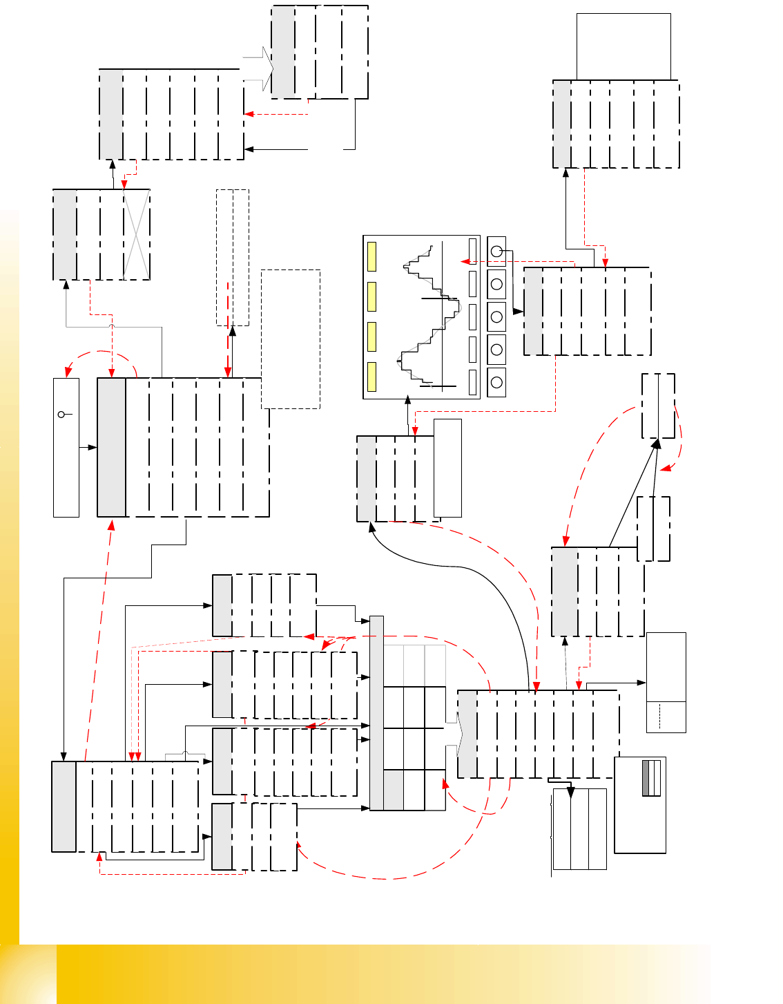
Fig. 20.2 - 1 Flow diagram of SIPLACE Axis Tester Version 1.5 in Expert mode
<-
|
TE
Samples 511, Time 0,5ms, Axis X,
Scale 3/4.3, Scope 15/-10, Range 40 ms,
Pull off: 2,001ms Ctrl.: 51.589ms
Pos.: 53,590ms Overshoot 2
X
Y
Z
DP
NC
Z
DP
NC
Z
IC
NC
D
IC
*
Board: 1, Axis X, Addr: 0
Top axis controll. M1
Middle axis cont. M2
Bottom axis cont. M3
Dynamic signals of
Boot and press ' '
Quit
Configuration
Machine
System control
Shutdown
About ...
Main menu
Compilation: Jul 04 2003
Serial number: 1234567
FPGA Version: 1.0
Free memory
Back
YES
Properties
Back
Select Axis
Pos. quality
Adjust panel
Track signals
Serial connect
Machine Info
Back
Track signals
Reference error
Line error
Usage see detail
description
Show all
Time > 5 ms
Quit
Back
<
_
|
f
.
m
e
a
s
m
.
<
_
|
f
.
m
e
a
s
u
r
m
e
n
t
Pos. quality
Back
Positioning time
Overspeed
Start the measure-
ment with <
_|
Proceeding
Quit
Back
Oscilloscope Mode
Start FFT
Start Plot
Proceeding
Back
Line 1
Line 2
Line 3
Line 4
Start the
Measurement
... with <
_|
Stop ... with
<
_|
..of
Pos.deviation
signal
Configuration
Back
Panel
Config Unit
Panel
Back
Selection 1
Selection 2
Selection 3
Selection 4
outputs for pos.qualit
y
output for Track signa
l
outputs for comparisio
n
act.pos. to end sig.
output
for internal signa
Panel
Back
Change Panel (single
Line)
Activate Panel
<
_|
727866 Axis is referenced
FW enabled servo
.....
F5 HM
CAN speed 1 MHz
Current axis
-> number of
axis controller
cards
Only now the desired
outputs are connected
to BNC
choose F-
machine
Back
C-Serie
SIPLACE HF
F Machine
S Machine
HS Machines
Choose Machine
choose C-
machine
Back
Back
F3
F4
F5
F5 HM
WPC
choose S-
machine
Back
G
S15
S20
S23/S25
S-27
choose HF-
machine
Back
HF
HF 3
HF 4
CS
CF

SIPLACE X Edition 09/2005
Appendix
5
This page shows a diagram Fig. 20.2 - 1 of the restricted ’Dummy mode’. This beginner mode
only provides access to the menus for axis dynamic testing/adjustment.
Fig. 20.2 - 2 Flow diagram of SIPLACE Axis Tester Version 1.5 in restricted ’Beginner" mode
<-
|
TE
Samples 511, Time 0,5ms, Axis X,
Scale 3/4.3, Scope 15/-10 , Range 40 ms,
Pull off: 2,001ms Ctrl.: 51.589ms
Pos.: 53,590ms Overshoot 2

Edition 09/2005 SIPLACE X
Appendix
6
20.3 ’SAT’ Machine Testing Menus
20.3.1 Exit
This menu saves the current settings and deactivates the system.
If the SIPLACE Axis Tester ’SAT’ is just unplugged, current settings won’t be saved for rebooting
but other problems will not occur.
If the ’SAT’ is disconnected from one axis controller and plugged into another, the SAT program
will remember the menu last used for a short time and will display it again after rebooting. To dis-
play the main menu, simply hit one of the keys!
20.3.2 Testing Track Signals
20.3.2.1 Displaying the Track Signals at the Axis Controller Input
This can be manually performed over the whole traversing range with the track signal tester for
the incremental encoder analog output signals. Representation of the digital track signals, to-
gether with manual axis displacement for fault analysis purposes, is not optimal, as it is difficult to
differentiate between slow displacement and track signal failure. However, the ’SAT’ can be re-
configured so that track signals can be tested at the axis controller input. This method shows the
BNC outputs with LNA ’Line A’ for track A or LNB for track B; a zero pulse index for the relevant
axis and, synchronously, the end signal (ENDE) at BNC 4.
The track sig-
nals can be
shown by:
- manual axis
displacement
(oscilloscope
set to trigger
mode ’Auto’)
or
- with an axis
positioning and
trigger signal at
the end signal
or zero pulse.
Fig. 20.3 - 1Con-
figuration of BNC
outputs
20.3.2.2 Testing Track Signals/Zero Pulse after a Gantry Axis Reference Run
As well as displaying track signals at the axis controller input, counting pulses can be tested along
the entire traversing range of the linear scale (even without oscilloscope representation).
Connect the SIPLACE Axis Tester SAT to the
respective Axis controller board
Boot the SAT and press ' ' to activate main menu
Select 'configuration'
Select 'Panel'
choose the desired 'Signals'
Selection 1 for Positioning quality/ Selection 2 for
Track signals/Selection 3 for actual pos.=nom.pos.-
End signal comparison/Selection 4 internal Signals
with Cursor up/down and confirm
with 'return' <-
|
Select menu 'Activate Panel'
Back to the menu 'Positioning quality'
Here you get the position deviation signal
to the SAT screen incl. time analysis.
The menu 'Back' returns back to
the previous menu level
This switches the signal to the SAT BNC-
output connectors
Default Signal combinations:
Selection 1Vnom/Vreg/ISoll/End
Selection 2 LNA/LNB/Index/End
Selection 3 LNA/LNB/Trigger/End