SiplaceX4_en.pdf - 第70页
1 - 46 S tudent Guide SIPLACE X 2 Overview Edition 09/2005 46 2.2.13.2 Construction of Single Conveyor The single conveyor c onsists of the input c onv eyor , two placements area s, intermediate conveyor and output conve…

1 - 45
Student Guide SIPLACE X
Edition 09/2005 2 Overview
45
Controlling the PCB inside the conveyors 2
The PCB is checked with light barriers (transmitter module and receiver module). The light barrier
transmitter is positioned below the conveyor belt and the receiver opposite to it, above the belt.
The light barriers stop the PCB in the input conveyor, intermediate conveyor and output conveyor.
The signal from the light barrier in the placement areas, triggers the brake application of the DC
motor and switches the laser (stopper) on. The PCB then moves in a set time (100ms) and with
reduced speed to the stop position (laser). The software-controlled brake application is adjusted
to suit the weight of the PCB, ensuring a constant travel time for all PCBs.
PCB stopper 2
The PCB in the placement area is stopped via a laser light barrier. The laser light barrier recog-
nizes the front edge of the PCB and stops it. This prevents the PCb hitting the stopper.
The position accuracy of the PCB is +/-0.5mm.
– A mechanical stopper for long boards up to 610mm is available as an option
Lifting table 2
Each placement area has one or two lifting tables working independently of one another (dual/sin-
gle conveyor). The lifting table is driven indirectly via a pneumatic cylinder controlled by a 5/2 way
valve. Different PCB thicknesses are automatically compensated. The vertical guide for the lifting
table plate (up/down) is defined at four points. The lifting distance is determined via an incremental
system.
The upper position is controlled via the measurement system with incremental encoder and a set
time period. The transport motor checks whether clamping was successful.
The lower position is checked via the measurement system and a proximity switch (BERO) on the
pneumatic cylinder, plus a set time period.
Additional we check the time which we need in both directions.
The clearance under the PCB is 40mm.
The old, 74 mm high, red PCB supports must not be used on the HF and Siplace X ma-
chines.
The dual conveyor can be used as an single conveyor when you move the conveyor rails of track
2 together (flexible dual conveyor).
1 - 46
Student Guide SIPLACE X
2 Overview Edition 09/2005
46
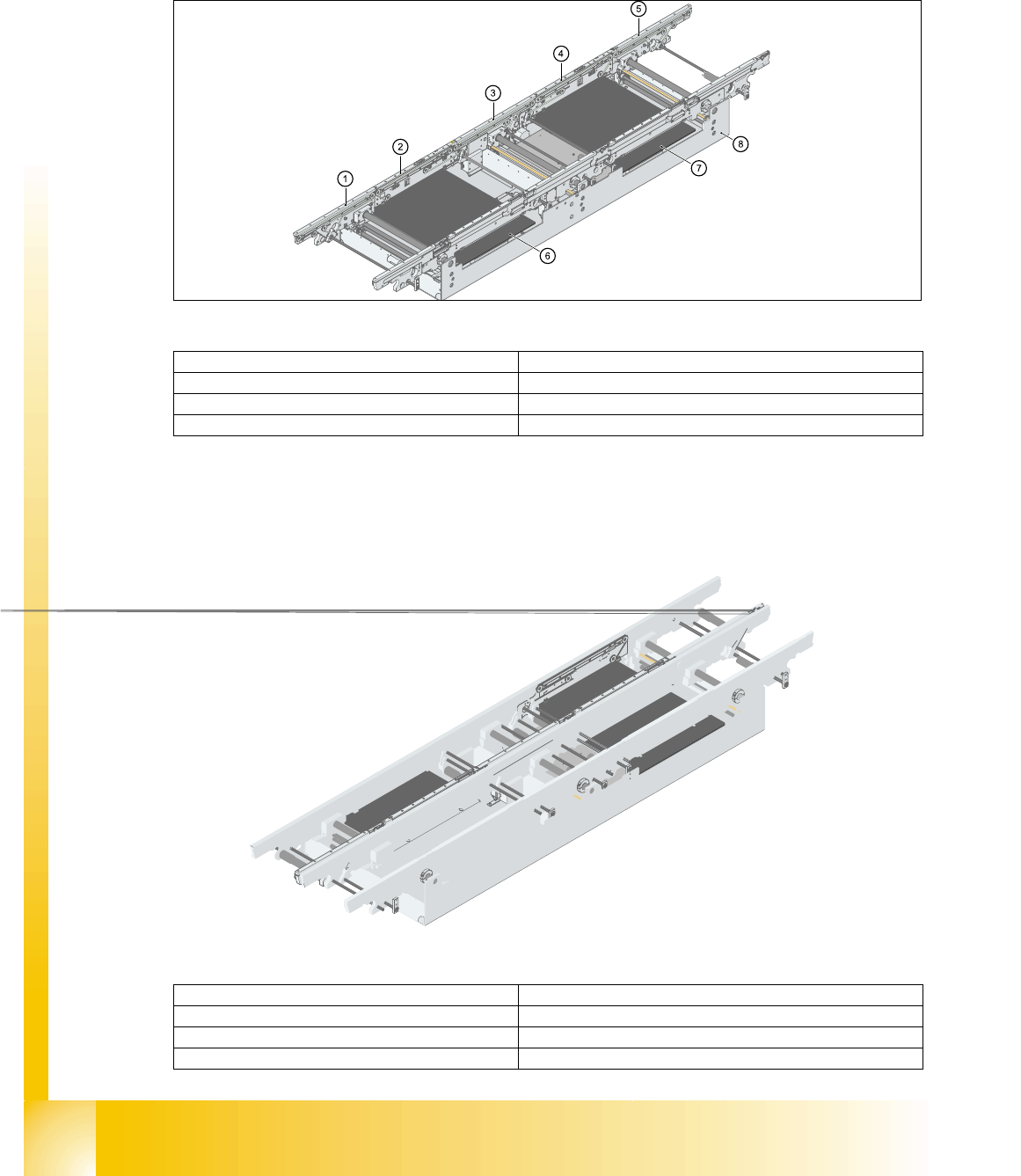
2.2.13.2 Construction of Single Conveyor
The single conveyor consists of the input conveyor, two placements areas, intermediate conveyor
and output conveyor. Each conveyor has automatic width adjustment and a lifting table for clamp-
ing the PCB.
Fig. 2.2 - 29 Construction of PCB conveyor
2.2.13.3 Construction of Dual Conveyor
Dual conveyors have two transportation tracks (1 and 2). In the standard conveyor, the right-hand
side of each track is the fixed side. The fixed conveyor side can be changed to the left, where re-
quired.
Fig. 2.2 - 30 Construction of dual conveyort
(1)Input conveyor (2)Conveyor for placement area 1
(3)Intermediate conveyor (4)Conveyor for placement area 2
(5)Output conveyor (6)Lifting table 1
(7)Lifting table 2 (8)Conveyor vat
(1)Input conveyor (2)Conveyor for placement area 1
(3)Lifting table 1 (4)Intermediate conveyor
(5)Conveyor for placement area 2 (6)Lifting table 2
(7)Output conveyor (8)Conveyor vat

Student Guide SIPLACE X
Edition 09/2005 Inhalt
1
Chapter
Table of contents
3 Communication and Control . . . . . . . . . . . . . . . . . . . . . . . . . . . . . . . . . . . . . . . . . . 3
3.1 Communication Overview. . . . . . . . . . . . . . . . . . . . . . . . . . . . . . . . . . . . . . . . . . . . . . . . . . . . . . . . . 3
3.1.1 Networking Overview. . . . . . . . . . . . . . . . . . . . . . . . . . . . . . . . . . . . . . . . . . . . . . . . . . 4
3.2 Networking Address . . . . . . . . . . . . . . . . . . . . . . . . . . . . . . . . . . . . . . . . . . . . . . . . . . . . . . . . . . . . . 5
3.2.1 Check the network addresses . . . . . . . . . . . . . . . . . . . . . . . . . . . . . . . . . . . . . . . . . . . 5
3.2.1.1 Stationscomputer . . . . . . . . . . . . . . . . . . . . . . . . . . . . . . . . . . . . . . . . . . . . . . . . . 5
3.2.1.2 Machinecontroller (MC) . . . . . . . . . . . . . . . . . . . . . . . . . . . . . . . . . . . . . . . . . . . . 6
3.2.2 Computer at the LAN Network . . . . . . . . . . . . . . . . . . . . . . . . . . . . . . . . . . . . . . . . . . 7
3.2.3 Communication on placement machine . . . . . . . . . . . . . . . . . . . . . . . . . . . . . . . . . . . 9
3.2.4 Machine Controller Communication . . . . . . . . . . . . . . . . . . . . . . . . . . . . . . . . . . . . . . 9
3.3 CAN Bus . . . . . . . . . . . . . . . . . . . . . . . . . . . . . . . . . . . . . . . . . . . . . . . . . . . . . . . . . . . . . . . . . . . . . . 11
3.3.1 History of CAN. . . . . . . . . . . . . . . . . . . . . . . . . . . . . . . . . . . . . . . . . . . . . . . . . . . . . . 11
3.3.2 CAN Bus in General . . . . . . . . . . . . . . . . . . . . . . . . . . . . . . . . . . . . . . . . . . . . . . . . . 13
3.3.2.1 11 Bit Identifier . . . . . . . . . . . . . . . . . . . . . . . . . . . . . . . . . . . . . . . . . . . . . . . . . . 14
3.3.2.2 CAN Bus protocol. . . . . . . . . . . . . . . . . . . . . . . . . . . . . . . . . . . . . . . . . . . . . . . . 14
3.3.2.3 CSMA: Collusion Detectection . . . . . . . . . . . . . . . . . . . . . . . . . . . . . . . . . . . . . . 15
3.3.2.4 CAN Bus Arbitration . . . . . . . . . . . . . . . . . . . . . . . . . . . . . . . . . . . . . . . . . . . . . . 15
3.3.3 CAN Bus Concept SiplaceX4 . . . . . . . . . . . . . . . . . . . . . . . . . . . . . . . . . . . . . . . . . . 17
3.3.4 CAN Bus Concept SiplaceX3 . . . . . . . . . . . . . . . . . . . . . . . . . . . . . . . . . . . . . . . . . . 18
3.3.5 CAN Bus Concept SiplaceX2 . . . . . . . . . . . . . . . . . . . . . . . . . . . . . . . . . . . . . . . . . . 19
3.3.6 CAN-Bus Concept with One Wire Bus e.g. SiplaceX3 . . . . . . . . . . . . . . . . . . . . . . . 20
3.3.7 CAN Bus Processor Board C&P Head . . . . . . . . . . . . . . . . . . . . . . . . . . . . . . . . . . . 21
3.3.7.1 CAN Bus controlled function on 6/12C&P Head. . . . . . . . . . . . . . . . . . . . . . . . . 21
3.3.7.2 CAN-Bus controlled function on C&P 20 Kopf . . . . . . . . . . . . . . . . . . . . . . . . . . 22
3.3.8 CAN Bus controlled function on the Twin Head . . . . . . . . . . . . . . . . . . . . . . . . . . . . 23
3.3.9 CAN I/O Module (SLIO) Siplace X. . . . . . . . . . . . . . . . . . . . . . . . . . . . . . . . . . . . . . . 24
3.3.9.1 DIP Switch on the Main- and Sub Distributor . . . . . . . . . . . . . . . . . . . . . . . . . . . 25
3.3.10 CAN: Bus Communication with Axis Controller. . . . . . . . . . . . . . . . . . . . . . . . . . . . 30
3.3.11 Communication Siplace Vision . . . . . . . . . . . . . . . . . . . . . . . . . . . . . . . . . . . . . . . . 31
3.3.11.1 Communication during a image acquisition . . . . . . . . . . . . . . . . . . . . . . . . . . . 32
3.3.12 Communikation C&P 20 Head. . . . . . . . . . . . . . . . . . . . . . . . . . . . . . . . . . . . . . . . . 33
3.3.13 Communication X-Feeder . . . . . . . . . . . . . . . . . . . . . . . . . . . . . . . . . . . . . . . . . . . . 34
3.4 Axis control . . . . . . . . . . . . . . . . . . . . . . . . . . . . . . . . . . . . . . . . . . . . . . . . . . . . . . . . . . . . . . . . . . . 35
3.4.1 Position measuring system . . . . . . . . . . . . . . . . . . . . . . . . . . . . . . . . . . . . . . . . . . . . 35
3.4.1.1 Track signals and Zero pulse signal . . . . . . . . . . . . . . . . . . . . . . . . . . . . . . . . . . 35