SiplaceX4_en.pdf - 第83页
1 - 7 S tudent Guide SIPLACE X Edition 09/2005 3 Communication and Control 7 3.3.2 CAN Bus in General – C AN is a serial bus syste m especially suit ed for networking devices as well as sensors and actuators within a sys…
1 - 6
Student Guide SIPLACE X
3 Communication and Control Edition 09/2005
6
tems (and their sensors) to exchange information. This was usually done by discrete interconnec-
tion of the different systems (i.e. point to point wiring). The requirement for information exchange
has then grown to such an extent that a cable network with a length of up to several miles and
many connectors was required. This produced growing problems concerning material cost, pro-
duction time and reliability.
The solution to this problem was the connection of the control systems via a serial bus system.
This bus had to fulfill some special requirements due to its usage in a vehicle. With the use of CAN,
point-to-point wiring is replaced by one serial bus connecting all control systems. This is accom-
plished by adding some CAN-specific hardware to each control unit that provides the ’rules’ or pro-
tocol for transmitting- and receiving information via the bus.
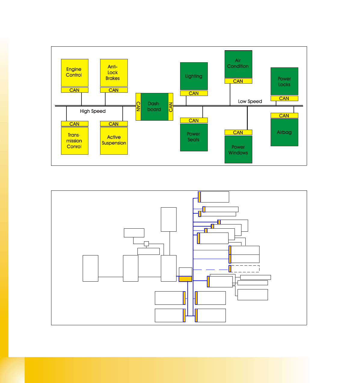
Fig. 3.3 - 3 Communication via CAN bus on example car controlling
Fig. 3.3 - 4 CAN communication on SIPLACE X machine
I/O Slio Board (SUB)
Transport
control
camera Illumination
control Board
Head Board gantry 3
Axis controller Board
Axis controller Board
Axis controller Board
I/O Slio Board (Main)
Line
computer
Station
computer
Machine
controller
LAN
Vision
system
MVS 100
H S
3
L Bus
Axis controller Board
Comp. table
controller
CAN Bus
Comp. table
controller
Comp.
Barcode
Transport
control
communi
cation
board
LAN
Comp. table
controller
Comp. table
controller
TSP 1 actors
PCB-Barcode
Keyboard
camera Illumination
control Board
Head Board gantry 1
TSP 2 actors
1 - 7
Student Guide SIPLACE X
Edition 09/2005 3 Communication and Control
7
3.3.2 CAN Bus in General
– CAN is a serial bus system especially suited for networking devices as well as sensors and
actuators within a system or subsystem.
– It is a bus system with multi-master capabilities, therefore all CAN nodes can request the
bus simultaneously.
– In CAN networks, there is no addressing of subscribers or stations in the conventional
sense, but instead, prioritized messages are transmitted. A transmitter sends a message to
all CAN nodes (broadcasting). Each node decide on the basis of the identifier received
whether it should process the message or not. The identifier determines the priority that the
message enjoys in competition for bus access. The relatively simplicity of the CAN chips
intergration make applications programming relatively simply.
– Each CAN message can transmit from 0 to 8 bytes of user information. Of course, you can
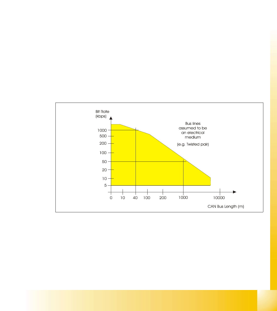
transmit longer data information by using segmentation. The maximum transmission rate is
specified as 1 Mbit/s. This value applies to networks about 40 m. For longer distances the
data rate must be reduced:
For distances up to 500 m a speed of 125 kbit is possible and for transmissions up to 1 km
a data rate of 50 kbit/s is permitted.
3
I
Fig. 3.3 - 5 CAN -bus length
The maximum CAN bus speed is 1 MBaud, which can be achieved with a bus length of up to 40
meters when using a twisted wire pair. For bus lengths longer than 40 meters the bus speed must
be reduced. A 1000 meter bus can still be released with a 50 KBaud bus speed. For a bus length
above 1000 meters special drivers should be used.
1 - 8
Student Guide SIPLACE X
3 Communication and Control Edition 09/2005
8
3.3.2.1 11 Bit Identifier
The CAN bus system is using the 11 Bit identifier for addressing the different CAN objects
Fig. 3.3 - 6 11 bit identifier
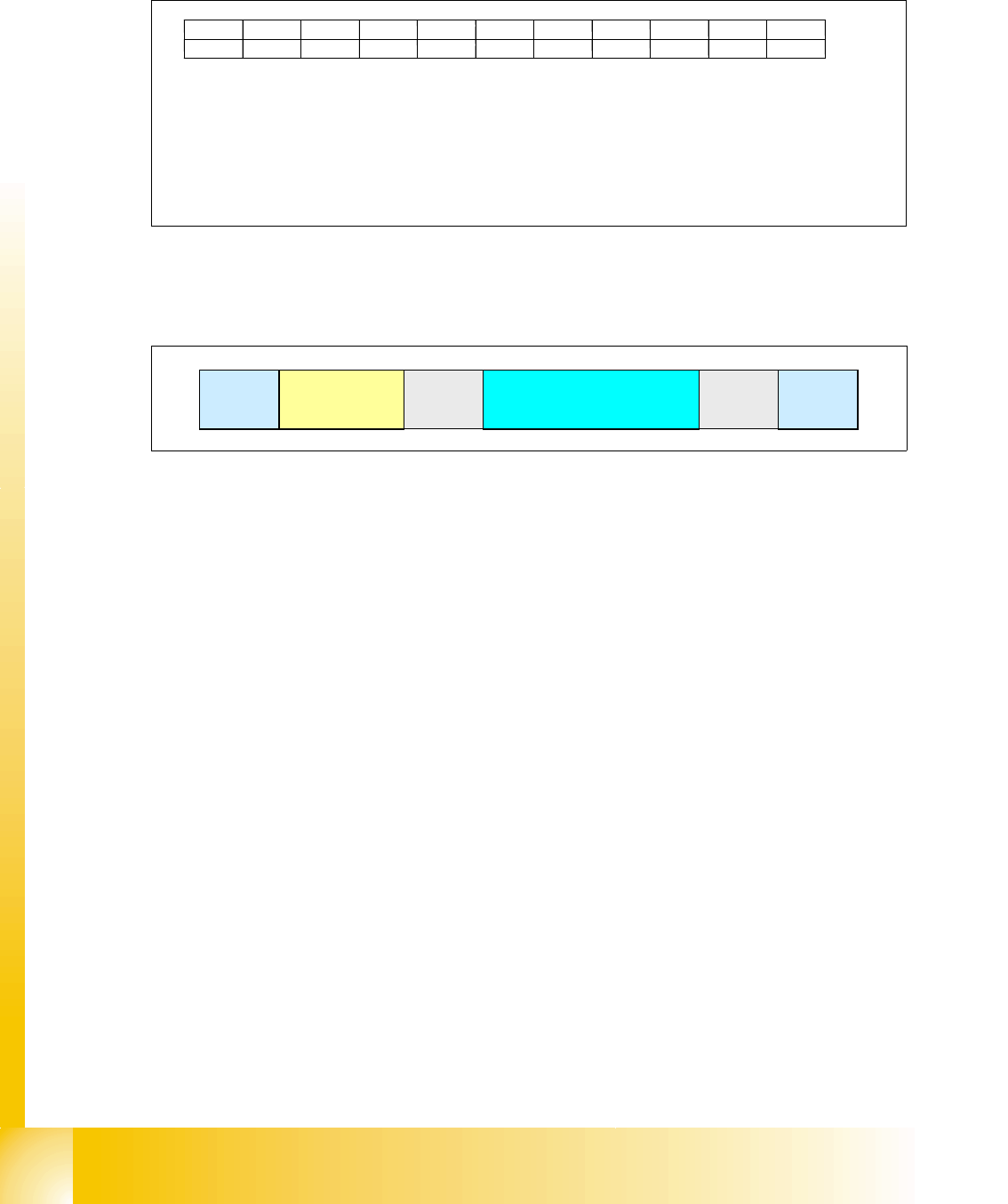
3.3.2.2 CAN Bus protocol
Fig. 3.3 - 7 CAN-bus protocol
Start: 3
– Determines the telegram start. After this bit is set, no other user of the CAN bus is able to
send. Even 2 or more user set this bit at the same time, the arbitration decides the highest
priority. The address with the highest priority is allowed to send the telegram.
Address: Identifier field (11 bit identifier) 3
– The value of this number is also the prority for the bus access.
Control information:
3
– Contains reserved bits and 4 bit DLC: Data Length Code.
Data field:
3
– Contains the user information from 0 byte to maximun 8 byte. The transfer of a byte begins
with the most significant bit (the bit with the highest value).
CRC sequence and CRC delimiter = CRC filed (cyclic redundancy check): 3
– Each message is combined with a CRC word. Therefore it recognizes messages which are
at least not in an origin state while disturbances.
End:
3
– The end of the length recognition is 7 bit.
Bit 10 Bit 9 Bit 8 Bit 7 Bit 6 Bit 5 Bit 4 Bit 3 Bit Bit 1 Bit 0
KKCCCCPPTTT
node type (K) CAN object (C) gantry number (P) telegram type (T)
depends on 00: section 1 000 command
node type 01: section 2 001 message
10: section 3
11: section 4
00: heads
01: axis
10: co table
11: reserved
start
address
(11 bit identifier)
control
information.
data (0-8 bytes user information) CRC
end