SiplaceX4_en.pdf - 第89页
1 - 13 S tudent Guide SIPLACE X Edition 09/2005 3 Communication and Control 13 3.3.5 CAN Bus Concept SiplaceX2 The placement machine SIPLACE HF3 uses a bus system w ith 1 Mbit/s transmis sion rate.The CAN: Bus system beg…
1 - 12
Student Guide SIPLACE X
3 Communication and Control Edition 09/2005
12
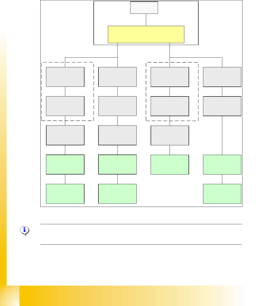
3.3.4 CAN Bus Concept SiplaceX3
The placement machine SIPLACE HF uses a bus system with 1 Mbit/s transmission rate.The CAN
Bus system begin at the Communication board and is split in 2 path. Every path is terminated by
a 120 ohm terminator on the head board at the individual placement head.
.
Fig. 3.3 - 12 CAN Bus overview Siplace X3
Note: When the Twin head is mounted, the switch for the terminator on the head board (C500)
have to be OFF. 3
SMP BUS
MC
MC
Computer Unit
C
O
M
U
n
i
t
CAN Bus cable
PA1
X6pn
Trailing Interface
Gantry 1
Transpor
t
Control unit
COT 1
Tape cutter
Axis unit
PA 1
CAN E/
A
Modu
l
Sektor
4
CAN E/
A
Modu
l
Sektor
4
CAN E/
A
Modu
l
Sektor
4
CAN I/O
SUB Modul
Sector 4
Vision
Control unit
Sector 4
COT 4
Tape cutter
SUB Distributor Sector 4
Trailing Interface
Gantry 4
Head board(C500)
Gantry 4
Terminator
(120 OHM)
Head board(C500)
Gantry 1
Terminator
(120 OHM)
CAN Bus cable
PA 2
X7pn
Main Distributor Sector 2
COT 3
Tape cutter
Axis unit
PA 2
Vision
Control unit
Sector 2
CAN I/O
Main Modul
Sector 2
COT 2 / MTC 2
Tape cutter
Terminator
120 Ohm
Trailing Interface
Gantry 3
Head board(C500)
Gantry 3
Terminator
(120 OHM)
1 - 13
Student Guide SIPLACE X
Edition 09/2005 3 Communication and Control
13
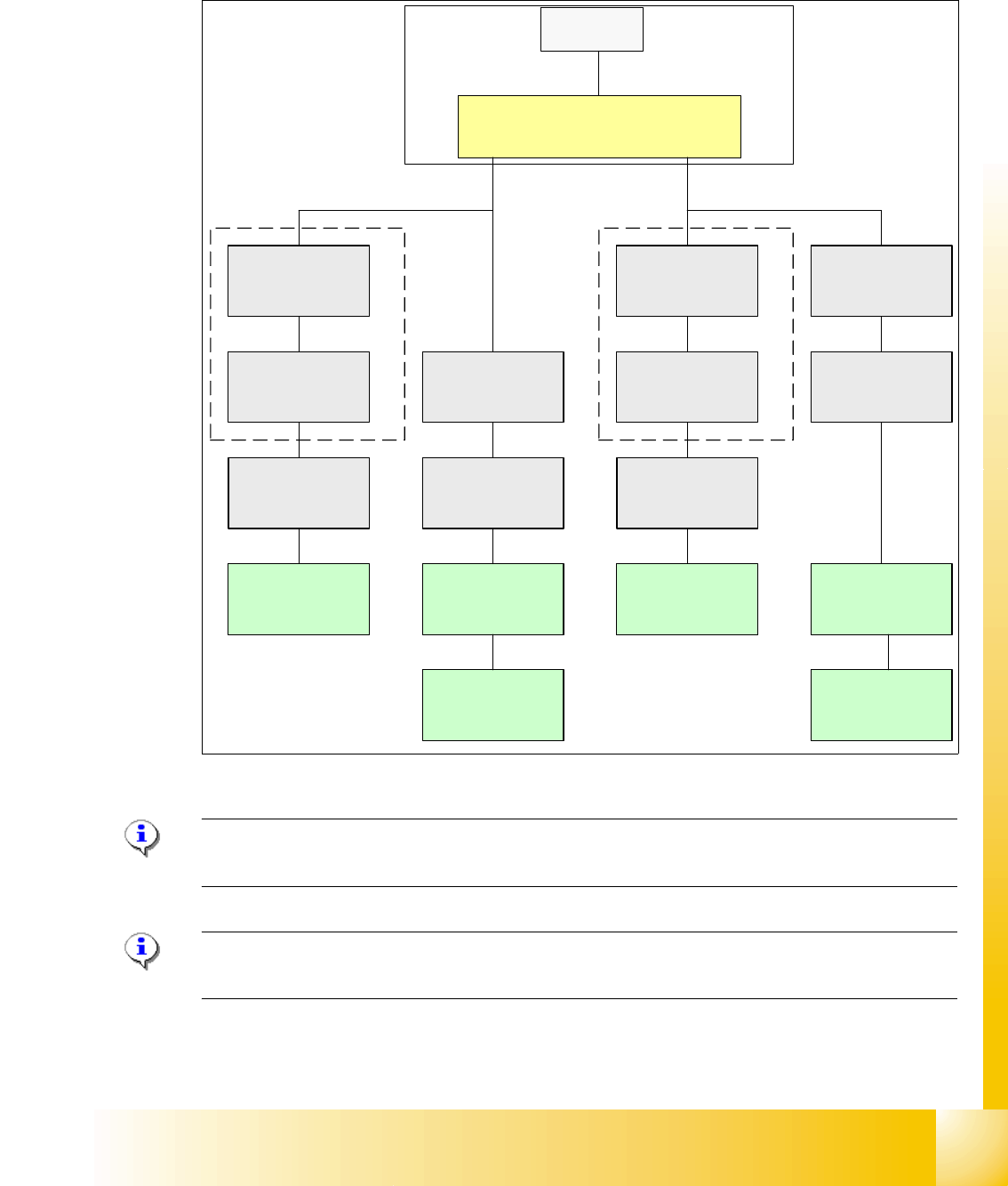
3.3.5 CAN Bus Concept SiplaceX2
The placement machine SIPLACE HF3 uses a bus system with 1 Mbit/s transmission rate.The
CAN: Bus system begin at the Communication board and is split in 2 path. Every path is termi-
nated by a 120 ohm terminator on the head board at the individual placement head.
Fig. 3.3 - 13 CAN Bus overall overview HF3
Note: When the Twin head is mounted, the switch for the terminator on the head board (C500)
have to be OFF. 3
Please Note: If you work with the Caccia (Diagnose Tool), please switch OFF the machine before
you connect the cable.
SMP BUS
MC
MC
Computer Unit
C
O
M
U
n
i
t
CAN Bus cable
PA1
X6pn
Trailing Interface
Gantry 1
Transport
Control unit
COT 1
Tape cutter
CAN E/
A
Modu
l
Sektor
4
CAN E/
A
Modu
l
Sektor
4
CAN E/
A
Modu
l
Sektor
4
CAN I/O
SUB Modul
Sector 4
Vision
Control unit
Sector 4
COT 4 / MTC2
Tape cutter
SUB Distributor Sector 4
Terminator
120 Ohm
Head board(C500)
Gantry 1
Terminator
(120 OHM)
CAN Bus cable
PA 2
X7pn
Main Distributor Sector 2
COT 3
Tape cutter
Axis unit
PA 2
Vision
Control unit
Sector 2
CAN I/O
Main Modul
Sector 2
COT 2 / MTC2
Tape cutter
Trailing Interface
Gantry 3
Terminator
120 Ohm
Head board(C500)
Gantry 3
Terminator
(120 OHM)

1 - 14
Student Guide SIPLACE X
3 Communication and Control Edition 09/2005
14
3.3.6 CAN-Bus Concept with One Wire Bus e.g. SiplaceX3
The placement machine SIPLACE HF/HF3 uses with the Software 505 an additional bus system,
which are integrated into the CAN Bus cable --> One Wire Bus.
With the Siplace X-machine the One Wire Bus is integreted in a separate CAT5 cabel, which start
from the Main- and Subdistributor up to the trailling interface. On the Main- and Subdistributor are
installed the control unit of the one wire system. A kind of switch are located on the other units
which required the one wire system (see figure below). This switch open and close the communi-
cation path.
Controlled components with the ONE Wire Bus:
– Nozzle changer of the C&P heads
– Temperature sensors
– Gantry recognition (CFK02, CFK04, CFK06)
– Option Reject Box
Fig. 3.3 - 14 General overview CAN-Bus with One Wire Siplace X3
Cat 5 (english category), is a Twisted-Pair-cabel, for data tranfer.
SMP BUS
MC
MC
Axis unit
PA 1
CAN Bus cable
Computer Unit
CAN E/
A
Modu
l
Sektor
4
CAN E/
A
Modu
l
Sektor
4
CAN E/
A
CAN I/O
SUB Modul
Sektor 4
COT 1
Tape cutter
SUB Distributor Sector 4
Main Distributor Sector 2
C
O
M
U
n
i
t
x
6
p
n
x
7
p
n
CAN Bus cable
One Wire
"Control unit"
One Wire
"Switch"
CAN Bus cable
with One Wire
COT 4
Tape cutter
Vision
Control unit
Sector 4
Trailing
cable-
Interface
Gantry 4
One Wire
"Switch"
Temperature sensor
Gantry recognition
One Wire
"Head interface"
Temperature sensor
Gantry recognition
One Wire
"Head interface"
Axis unit
PA 2
COT 3
Tape cutter
One Wire
Hub
One Wire
"Switch"
Temperature sensor
Gantry recognition
One Wire
"Head interface"
CAN I/O
Main Modul
Sector 2
One Wire
"Control unit"
CAN Bus cable
with One Wire
Transport
Control
unit
Nozzle
changer A/B
COT 2 / MTC
Tape cutter
Vision
Control unit
Sector 2
Nozzle
changer A/B
One Wire
Hub
One Wire
Hub
Nozzle
changer A/B
One Wire
Hub
Trailing
cable-
Interface
Gantry 1
Trailing
cable-
Interface
Gantry 3