SiplaceX4_en.pdf - 第94页
1 - 18 S tudent Guide SIPLACE X 3 Communication and Control Edition 09/2005 18 3.3.9 CAN I/O Module (SLIO) Siplace X T wo CAN Bus I/O modules are integrated in the dif ferent section of the HF/HF3/X machine. Both modules…
1 - 17
Student Guide SIPLACE X
Edition 09/2005 3 Communication and Control
17
3.3.8 CAN Bus controlled function on the Twin Head
The CAN-Bus Processor-board is no longer on each Twin segment installed. Now, the Twin seg-
ment got a new board and the processor board (TQM) is installed on the head board C500. The
reason is, that we have a defined interface for head modularity.
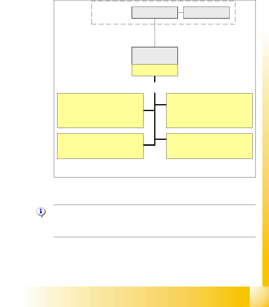
Fig. 3.3 - 17 Function on the Can Bus Processor Twin Head
NOTE:
The status of the 16 bit PROCESSOR BOARD is indicated on the 7-segment display.
Normal status on the diplay is: " . " flashed
(Description of the 7-segment display see chapter C&P Head).
Vacuum/Air kiss generator Segment 1
1. Adjust vacuum/air kiss
2. Measurement vacuum/air kiss
3. Reject function
Computer Unit
COM Board
Machine- CAN Bus
(1MBit/s)
Control of the following functions
MC
Head processor
C500
TQM-module
Force measurement board Segment 1
1. Activation
Function control force measurement
directly on the axis controller A363
Vacuum/Air kiss generator Segment 2
1. Adjust vacuum/air kiss
2. Measurement vacuum/air kiss
3. Reject function
Force measurement board Segment 2
1. Activation
Function control force measurement
directly on the axis controller A363
1 - 18
Student Guide SIPLACE X
3 Communication and Control Edition 09/2005
18
3.3.9 CAN I/O Module (SLIO) Siplace X
Two CAN Bus I/O modules are integrated in the different section of the HF/HF3/X machine. Both
modules are fully identical
Product characteristics:
– micro controller with integrated CAN controller
– data memory
– programm memory (flash)
– CAN interface with 9 pin connector and address alignment
– 16 digital Output 24 V with status LED
– 24 digital Input 24 V with status LED
– download interface
– power supply 5 V and 24 V
– extended Board on the I/O Module for "One Wire Bus"
Attention: two different kind of CAN I/O modul 00355051-01/02 with an additional RS232
bridge and 00355051-03 with integrated RS232 bridge. (TI 2005-08E03)
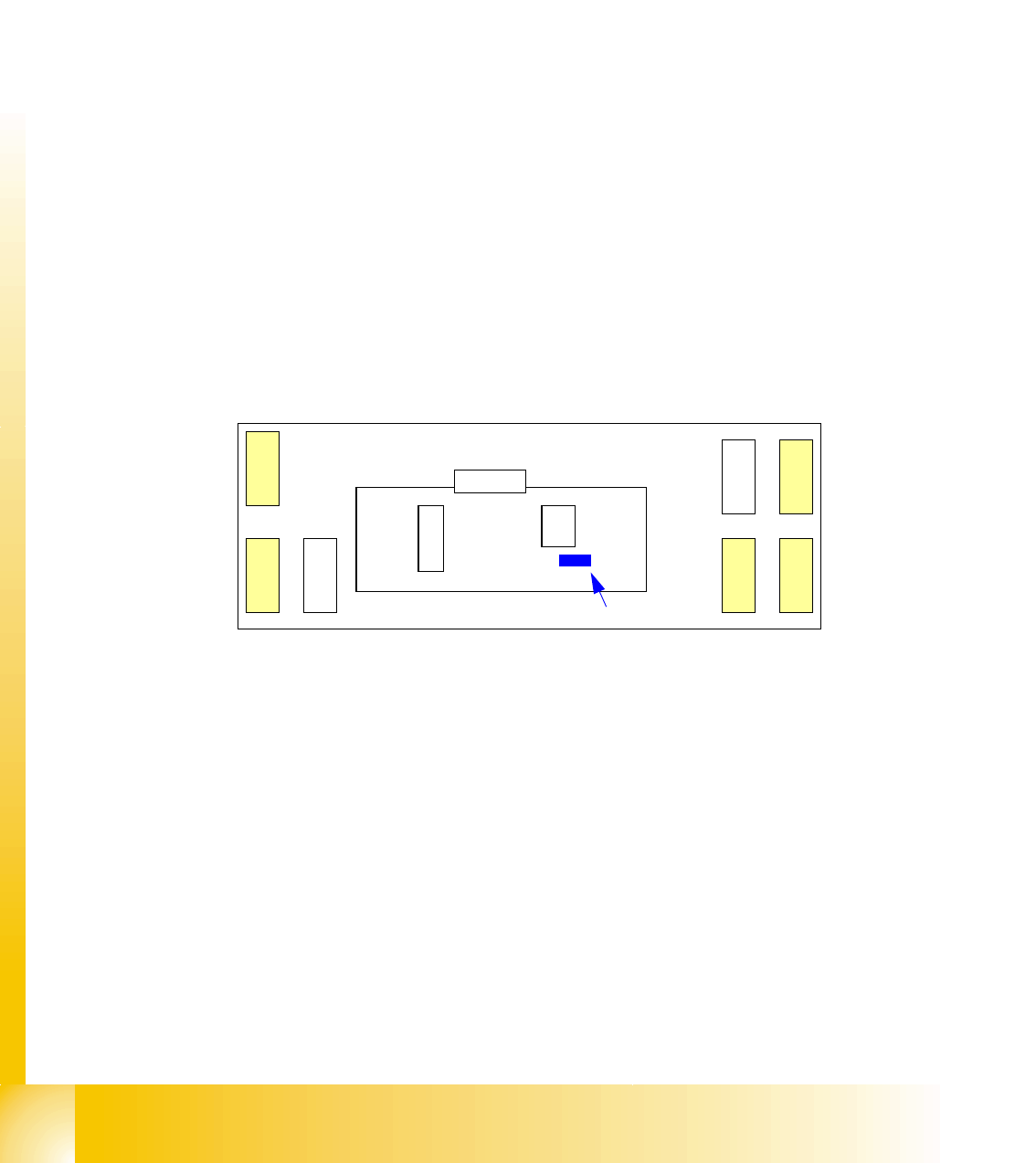
Fig. 3.3 - 18 Overview CAN I/O module
Legend
(1) DIP switches ONE Wire board have Paßtrough connectors for
CAN-Bus and RS 232.
X1 CAN-Interface on "ONE Wire Board" RS232 analog interface, bootstraploader inter-
face
X3, X4, X5 digital inputs 24V X6 power supply 5V
X7, X8 digital outputs 24V X9 power supply 24V
X7
X
1
R
S
2
3
2
X3, X4, X5 digital input
X7, X8 digital output
CAN I/O module
X
8
X
9
X
3
X
4
X
6
X
5
One Wire
Board
(1)
Jumper
X2
1 - 19
Student Guide SIPLACE X
Edition 09/2005 3 Communication and Control
19
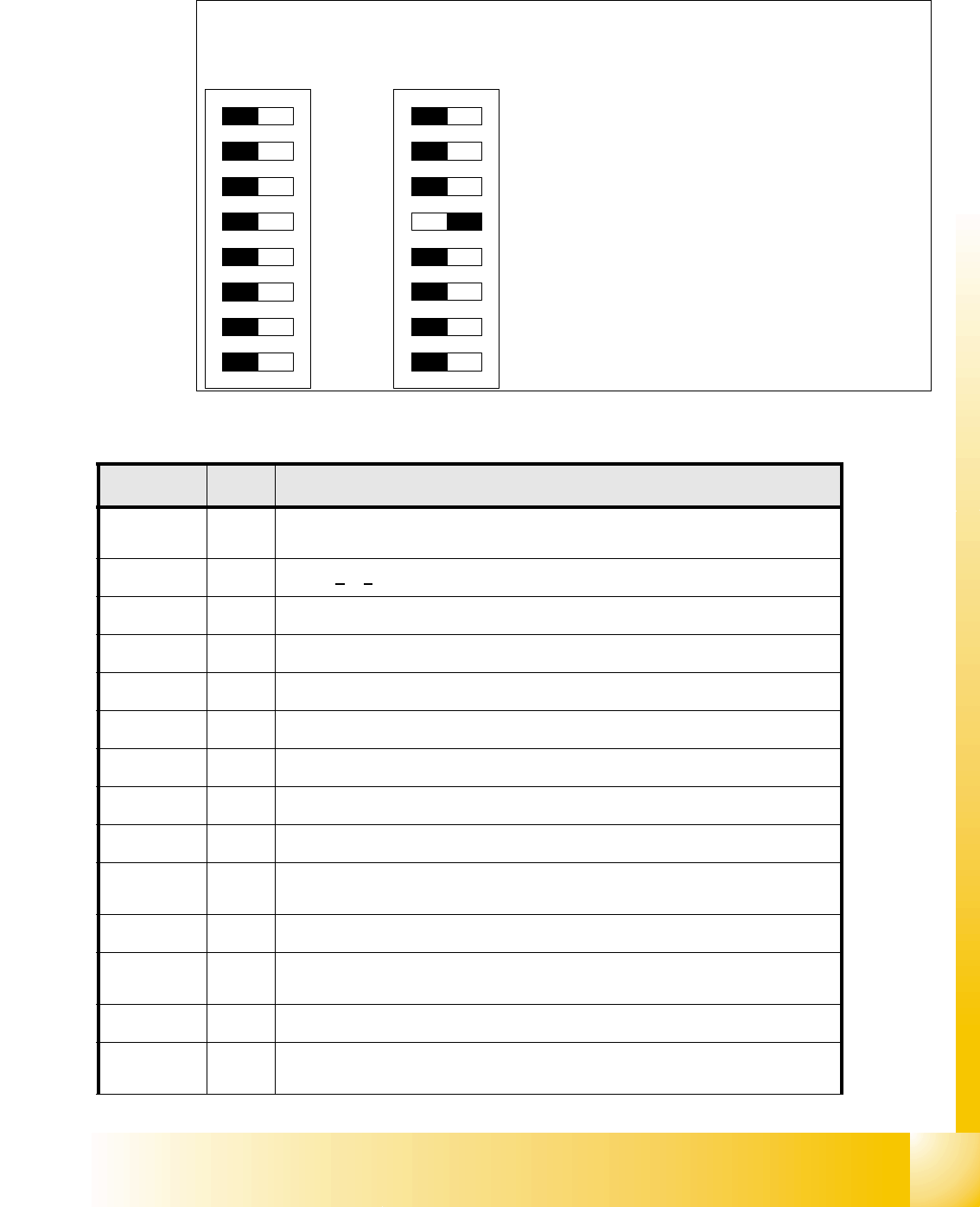
3.3.9.1 DIP Switch on the Main- and Sub Distributor
I/O Module Main Distributor: (Inputs) 3
DIP Switch
O
N
78123456
O
N
78123456
Main
Distributor
Sub
Distributor
Description DIP Switch:
1 CAN Address 0
2 CAN Address 1
3 CAN Address 2
4 CAN Address 3
5 not used
6 not used
7 not used
8 Terminator CAN Bus
Connectors I / O Description / Note
X3_1 Di0
M_E-Stop Loop1ok or M_Security Loop(
"high" signal if all safety loops closed
(Covers, E-Stop Buttons, Feeder flaps, COT‘s).
X3_2 Di1
nc is
not connected (Reserved)
X3_3 Di2
nc
X3_4 Di3
M_Feeder Flaps (
"high"signal if one or more flaps open.)
X3_5 Di4
nc
X3_6 Di5
nc
X3_7 Di6
nc
X3_8 Di7
nc
X4_1 Di8
nc
X4_2 Di9
M_Ready / This message is changed from
"low" to "high" if the SSK (K6)
latched, only possible if "Control ON".
X4_3 Di10
M_Pressure sensor (reserved)
X4_4 Di11
M_GantryCrash1
"low" Signal gantry 1 and 4 to close , "high" Signal normal
status
X4_5 Di12
nc
X4_6 Di13
M_ServoEnable1 or Control ON /
"high" Signal - intermediate circuit voltage
for X/Y Servo on Axis Unit1 goes through.(K4 message)