SIPLACE S-23 HM User Manual - 第30页
30 ’Single functions PCB transport 1’ menu ↑ UM 5.3 This menu is used for ch ecking an d setting the function modules of th e PCB convey or . If the twin conve yor option is installed, th e Single fun ctions PCB transp o…
29
Return all nozzles All nozzles are returned to the magazine of the nozzle changer.
Pick up all nozzles The revolver head picks up all nozzles from the nozzle magazine.
Remove all nozzles All of the nozzles in the revolver head are discarded into the rejects con-
tainer.
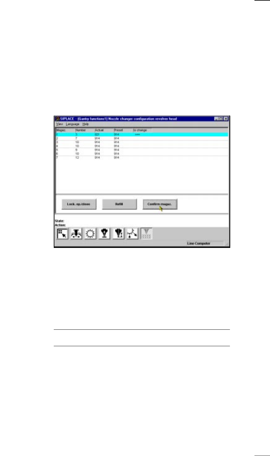
’Nozzle-changer configuration revolver head’ menu
↑ UM 5.2.6 Within this menu you can
– find out the nozzle types of the individual magazines
– check nozzles and
– change nozzles.
Magazine: Magazine number, maximum 7
Number: Number of nozzles in the magazine
Actual: Setup currently in the nozzle changer
Preset: Setup specified by the line computer
Arrow: If preset and actual values differ, this will be indicated by an arrow.
Lock. op./close You can open or close the closing plate of the selected nozzle changer
magazine in order to fill the nozzle changer magazine manually.
Refill: Refill the magazine with new nozzles of the same type and click on ’Refill’.
The fill level is updated.
NOTE
Make sure that the nozzle magazines are kept full.
Confirm magazine: Set up the nozzles as required in the magazine indicated by an arrow.
– Move the cyan bar over the corresponding line in the list field.
– Click on ‘Confirm magaz.’. The desired and actual values must agree.
30
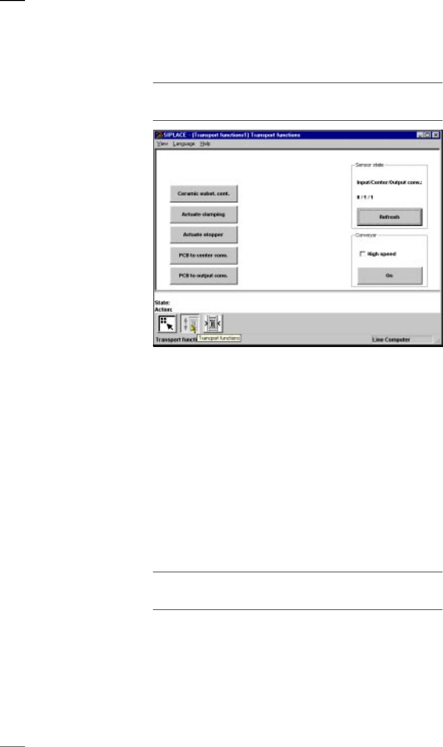
’Single functions PCB transport 1’ menu
↑ UM 5.3 This menu is used for checking and setting the function modules of the
PCB conveyor. If the twin conveyor option is installed, the Single functions
PCB transport 2 menu will be activated. The same functions as with PCB
transport 1 will then be available to you.
NOTE
To move the gantries, close the covers and then press the start button. All
gantry and head axes will move at low speed.
PCB The PCB is transported from the input conveyor onto the center conveyor
to center conveyor and then stopped and clamped.
PCB The PCB is transported from the center conveyor onto the output
to output conveyor conveyor.
The following menu items behave like a toggle switch when clicked on.
Ceramic substrate Click on the Ceramic substrate centering button and the substrate
centering (option) centering clamp will be activated or deactivated.
Actuate clamping Click on the Actuate clamping button and the clamp will be activated or
deactivated.
Actuate stopper Click on the Actuate stopper button and the stopper will be moved in and
out of position.
Sensor You can use this menu item to interrogate the states of the ultrasonic
Input/center/output beros in the input, center and output conveyors:
Refresh 1 = has responded
0 = has not responded
Conveyor - Select different speeds for the conveyor width adjustment.
high speed
NOTE
Make sure that there are no boards on the conveyor belts. The input belt
runs at high speed only.
Conveyor - On This starts the conveyor belts.
31
● Click on OK in the dialog box to cancel the procedure.
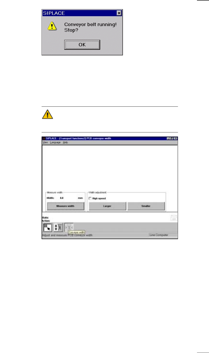
’PCB conveyor width’ menu
↑ UM 5.3.2 This menu is used for measuring and adjusting the conveyor belt width.
CAUTION
Make sure there are no boards on the conveyor belts when you adjust the
conveyor belt width.
Measure width Press this button to display, measure and save the width of the PCB trans-
port.
Width adjustment With this menu item you can adjust the width of the PCB conveyor at a
higher or lower speed as you like. If you have changed the width when
you quit the Single functions menu, the conveyor width will be measured
with the left-hand gantry and updated. Access this menu once again to
see the current width.