SIPLACE S-23 HM User Manual - 第35页
35 PCB barcode error (option) If it was not possible to read the b arcode p roperly , the following sele ction and dialog box will b e displayed on the scre en. ● Use the key board to enter the cor rect bar c ode or ● tr…

34
Fiducial errors
This error message will be displayed if it was not possible to find or detect
a fiducial.
● Click on OK to acknowledge and then select from the functions displayed:
Abort processing With this function you can abort processing.
Continue processing With this function you can continue processing.
Display errors menu With this function you can display the list of the machine errors which have
occured on the screen.
Single functions Select this menu to correct the error.
Gantry
Resume placement • Transport the board onto the output conveyor.
of PCB without • Replace the board on the input conveyor.
components loss • Transport the board onto the center conveyor. The board
is stopped there and clamped.
• Now select Continue placement.
Nozzle configuration errors
If an error occurs in connection with the nozzle configuration or if the con-
figuration has to be changed, the warning box Nozzle configuration error
Gantry 1/2 will be displayed on the screen.
● Click on OK to acknowledge.
SF Gantries 1/2 menuSelect the submenu Nozzle configuration revolver head and
change the nozzle.
When you quit the SF menu, a head reference run and a height reference
run with vacuum test will be carried out.
Continue processing With this function you can continue processing.
35
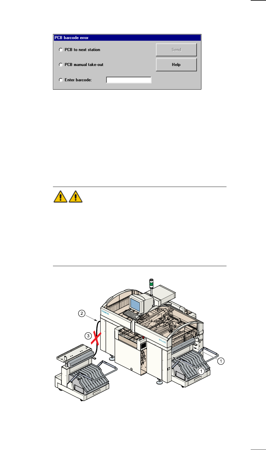
PCB barcode error (option)
If it was not possible to read the barcode properly, the following selection
and dialog box will be displayed on the screen.
● Use the keyboard to enter the correct bar code or
● transport the board.
Continue processing With this function you can continue processing.
Docking and Undocking the mobile component table
Safety instructions for docking and undocking the mobile component table
WARNING
● Never reach into the gap between the component tables and the place-
ment system frame while the machine is running (item 1).
● Always check that the component table is docked on the placement sys-
tem before connecting or disconnecting the component table power cable
at the socket on the placement system (item 2).
● NEVER connect the component table connecting cable to the socket on
the placement system and then operate the component table via the
external compressed air control unit (item 3).
36
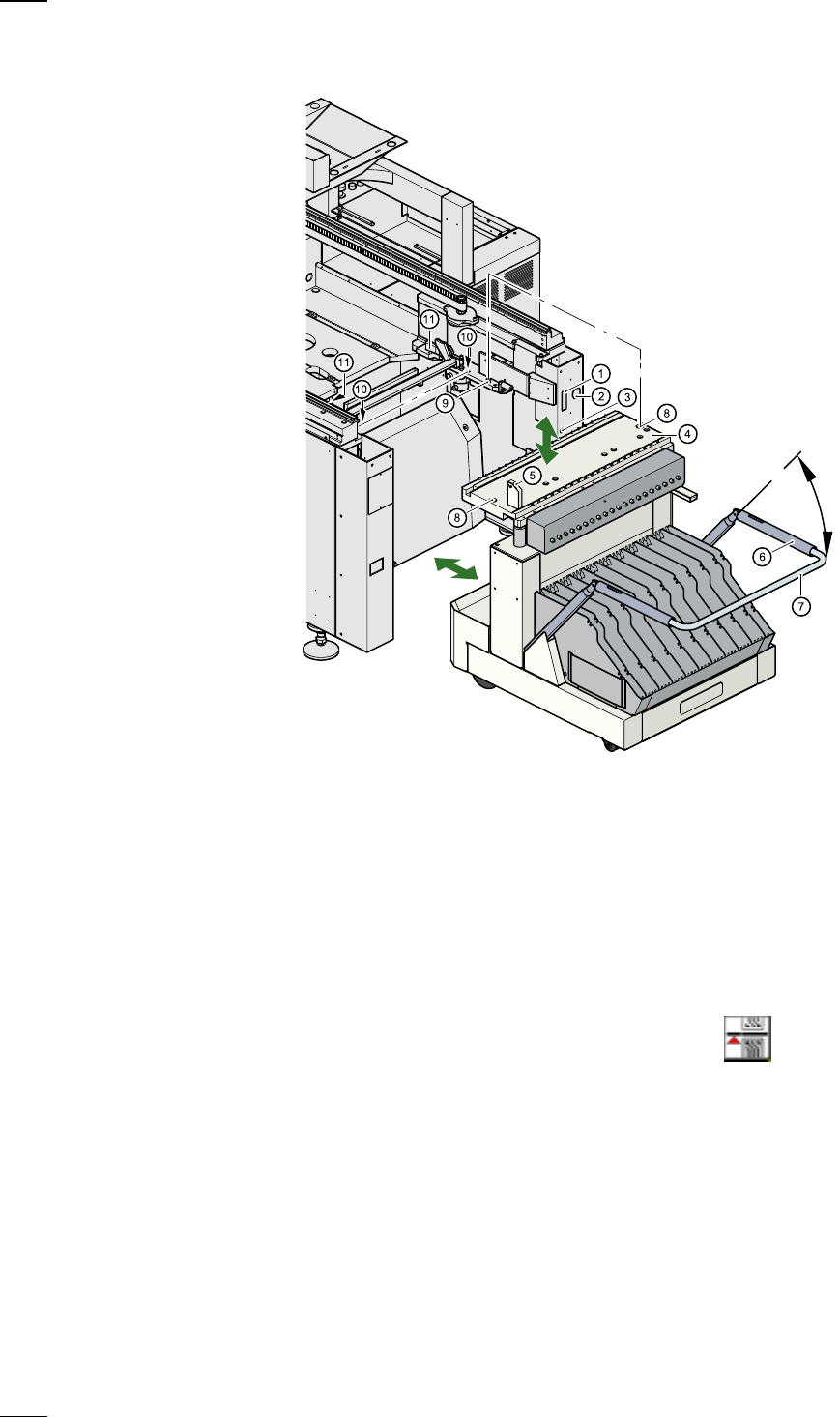
Undocking the component table
a
Communication interface connector
s Power supply connector for the component table
d Compressed air connection
f Component table bed
g Button for raising and lowering the component table bed
h Actuating tube
j Fold-down bracket
k
Holes for the centering pins
l Centering pins
; Contact surfaces for the slide rails of the component table
A Horizontal tensioners
● Click on the
STOP PROCESSING PCB icon in the MAIN VIEW menu.
● The PCB in progress will be completed. The icons of the SINGLE FUNC-
TIONS menu will then be activated.
● Click on the desired SINGLE FUNCTIONS GANTRY X icon (gantry 1
or 2).
● Click on the GANTRY FUNCTIONS icon.
● From this menu, click on the GO TO SET-UP POSITION button.
● The selected placement head will move across the PCB transport to pre-
vent it being damaged when the component table is changed.
● Open protective cover of the selected gantry.
● Open the side screens.