SIPLACE S-23 HM User Manual - 第5页
5 Abbreviations The followin g abbrev iations are em ployed in this quick ref erence g uide: DEV Originator of the error BC Barcode BE, Cmp, C O Component SF Single funct ions #E Error counte r GF Package for m PCB, LP P…

4
Troubleshooting . . . . . . . . . . . . . . . . . . . . . . . . . . . . . . . . . . . . . . . . . . . . . . . . . . . . . . . . . . . 32
Empty track errors. . . . . . . . . . . . . . . . . . . . . . . . . . . . . . . . . . . . . . . . . . . . . . . . . . . . . . . 32
Machine errors . . . . . . . . . . . . . . . . . . . . . . . . . . . . . . . . . . . . . . . . . . . . . . . . . . . . . . . . . 33
Transport errors . . . . . . . . . . . . . . . . . . . . . . . . . . . . . . . . . . . . . . . . . . . . . . . . . . . . . . . . 33
Fiducial errors . . . . . . . . . . . . . . . . . . . . . . . . . . . . . . . . . . . . . . . . . . . . . . . . . . . . . . . . . . 34
Nozzle configuration errors. . . . . . . . . . . . . . . . . . . . . . . . . . . . . . . . . . . . . . . . . . . . . . . . 34
PCB barcode error (option). . . . . . . . . . . . . . . . . . . . . . . . . . . . . . . . . . . . . . . . . . . . . . . . 35
Docking and Undocking the mobile component table . . . . . . . . . . . . . . . . . . . . . . . . . . . . . . 35
Safety instructions for docking and undocking the mobile component table. . . . . . . . . . . 35
Undocking the component table . . . . . . . . . . . . . . . . . . . . . . . . . . . . . . . . . . . . . . . . . . . . 36
Docking the component table . . . . . . . . . . . . . . . . . . . . . . . . . . . . . . . . . . . . . . . . . . . . . . 37
Index . . . . . . . . . . . . . . . . . . . . . . . . . . . . . . . . . . . . . . . . . . . . . . . . . . . . . . . . . . . . . . . . . 39
Flowchart "Switching ON the SIPLACE Line" . . . . . . . . . . . . . . . . . . . . . . . . . . . . . . . . . . . . 43
5
Abbreviations
The following abbreviations are employed in this quick reference guide:
DEV Originator of the error
BC Barcode
BE, Cmp, CO Component
SF Single functions
#E Error counter
GF Package form
PCB, LP Printed circuit board
Seg Segment
TR/D/T Track/Division/Tray
↑ UM See User Manual, section ...
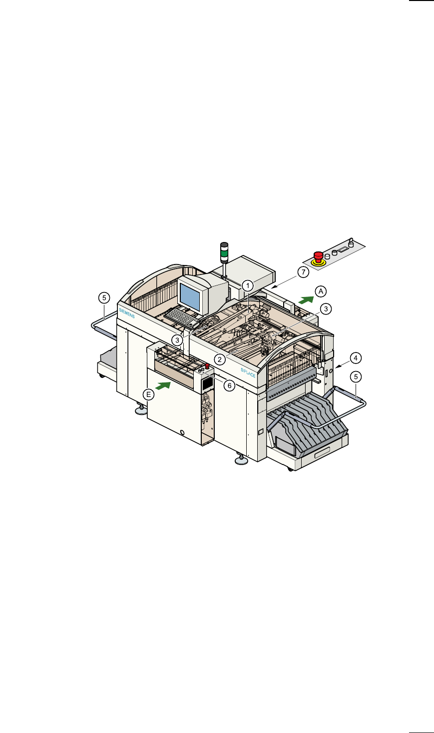
Structure of the placement system
Switches and buttons on the placement system
The following diagram shows the positions of the switches and buttons on
the placement system.
a
Gantry 1
s
Gantry 2
d
12-segment revolver head
f
Sockets for the component changeover table cable
g
Component changeover table
h
Controls, input side
j
Controls, output side
A PCB conveyor - output side
E PCB conveyor - input side
6
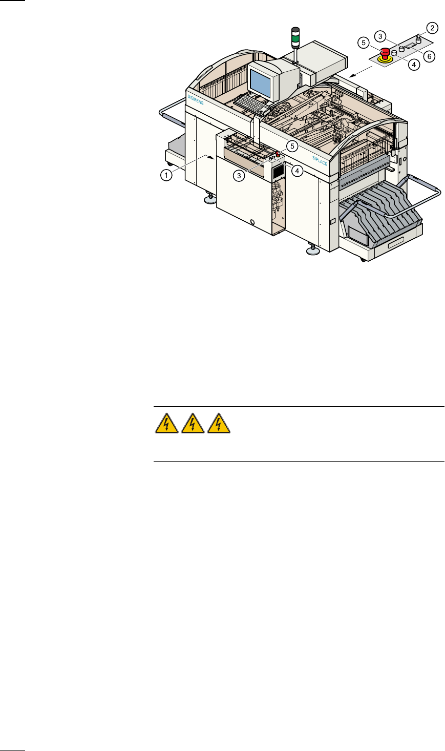
Main switch
The main switch is used to switch the power supply to the placement sys-
tem on and off.
RISK OF DEATH
Certain parts inside the placement system continue to carry potentially
lethal voltages even when switched off at the main switch.
Key switch
The key switch is normally set to the "0" position during operation. The key
should be removed and kept in a safe place. Only authorised personnel
may turn it to the "I" position (line engineer mode), and then only for cer-
tain maintenance or servicing work.
Stop button
This button is used to stop placement on the placement system.
Start button
Use this button to start the placement system after switching on or elimi-
nating a fault.
Emergency stop mushroom-head push-button
The emergency stop mushroom-head push-button latches in place when it
is pressed. The power supply to the gantry axes, component changeover
tables, conveyor belts and cutting devices is interrupted and the power
a
Main switch (red with yellow enclosure)
s
Key switch
d
Stop button (black)
f
Start button (white)
g
Emergency stop mushroom-head push-button
h
Component counter