SIPLACE S-23 HM User Manual - 第8页
8 Component barcode reader (option) There is a compartment f or a Datalogic DL 910 comp onent barcod e reader betw een the keyboard and the scre en. The barco de reader enables th e compon ents to be set up and topped u …
7
supply for the star axes of the placement heads is reduced. Turn the but-
ton to release it.
Component counter
The component counter shows the number of components that have been
processed.
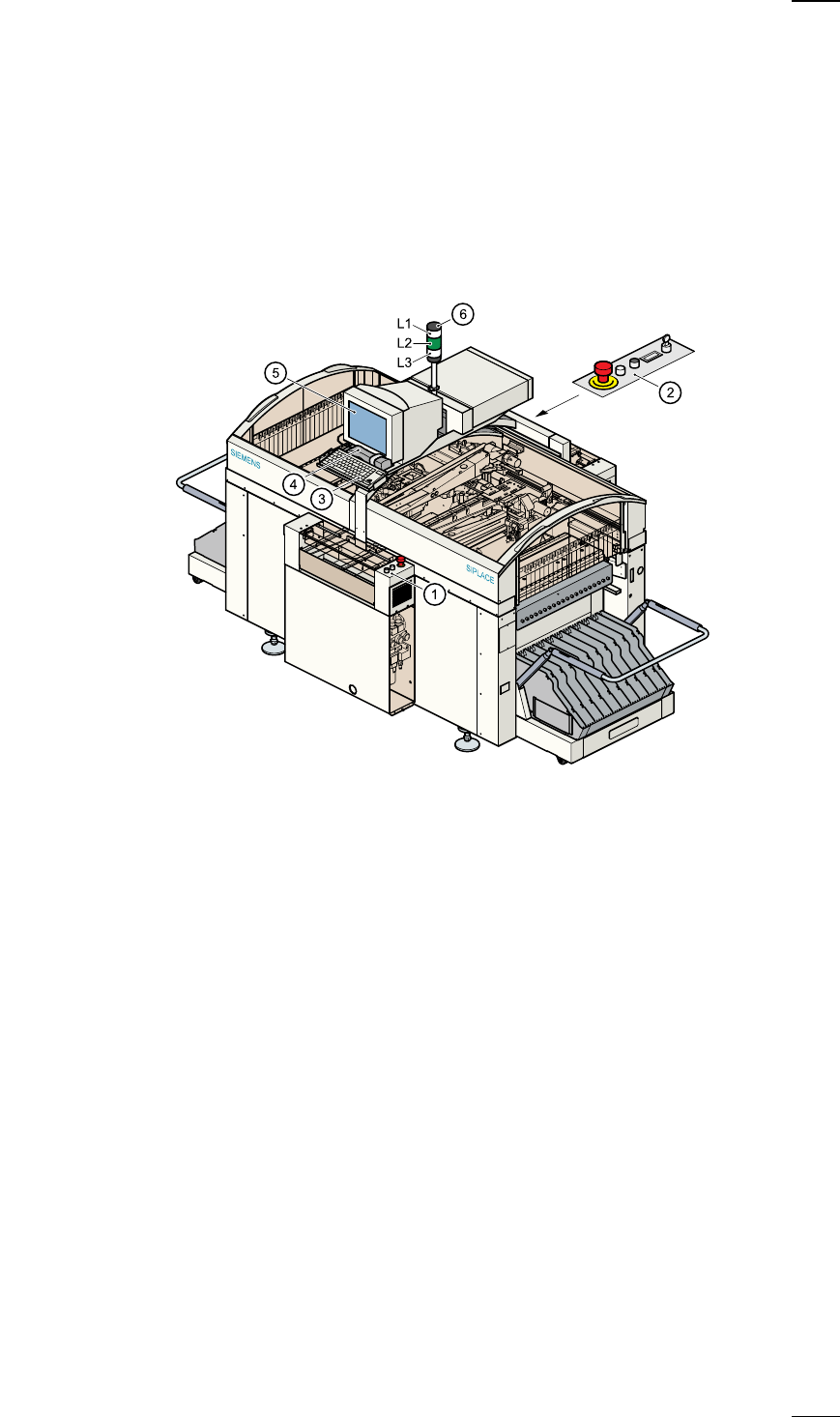
Displays and controls
The following diagram shows the displays and controls.
Description of the displays and controls
All the controls can be reached by anyone who is more than 1.60 m tall.
Touchscreen
As an alternative to the trackball you can position the mouse pointer on
the screen and operate it by touching the screen with your finger. The
resolution is 640 x 480 pixels.
Keyboard with integral trackball
The keyboard and trackball are located beneath the screen. The keyboard
can be raised and lowered.
a
Controls, input side
s
Controls, output side
d
Keyboard with integral trackball
f
Component barcode reader
g
Touchscreen
h
Main fault indicator
L1 White fault indicator lamp: gantry 2, location 3
L2 Green operating status lamp
L3 White fault indicator lamp: gantry 1, location 1

8
Component barcode reader (option)
There is a compartment for a Datalogic DL 910 component barcode
reader between the keyboard and the screen. The barcode reader
enables the components to be set up and topped up quickly and reliably.
Main fault indicator
The sequence of colours of the indicator lamp is white (L1) - green (L2) -
white (L3). It signals different operating statuses and faults on the place-
ment system.
Functional description of the main fault indicator
Main fault indicator
General operating statuses
–
Operating status lamp (green) on continuously
The placement system is in service
–
Operating status lamp (green) flashes
The placement system is waiting for a PCB on the input belt or the place-
ment system is waiting until the output belt is free.
–
Top white fault indicator lamp L1 flashes
One or more tracks are empty on the right-hand side of the placement
system. The placement system continues to place any remaining compo-
nents.
–
Bottom white fault indicator lamp L3 flashes
One or more tracks are empty on the left-hand side of the placement sys-
tem. The placement system continues to place any remaining compo-
nents
–
Top white fault indicator lamp (L1) on continuously - green operating sta-
tus lamp (L2) off
An error has occurred on the right-hand side of the placement system ->
the placement system has stopped.
–
Bottom white fault indicator lamp (L3) on continuously - green operating
status lamp (L2) off
An error has occurred on the left-hand side of the placement system ->
the placement system has stopped.
–
Both white fault indicator lamps (L1 and L3) on continuously - green oper-
ating status lamp off
An error has occurred that affects the entire placement system -> the
placement system has stopped.
L1: Fault indicator lamp (white)
L2: Operating status lamp (green)
L3: Fault indicator lamp (white)
9
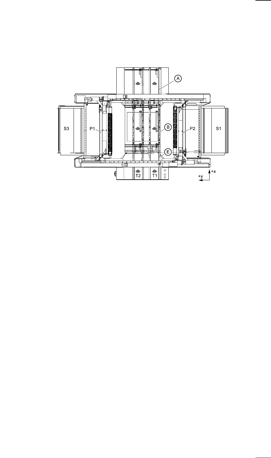
Machine Areas
The figure below provides a diagrammatic overview of the individual areas
of a SIPLACE S-23 HM placement station.
The terms used in the figure to describe these areas are also used in the
texts in the user interface and in the User Manual.
The PCB conveyor is divided into the following sections:
– Input conveyor
– Processing conveyor
– Output conveyor
A Output conveyor
E Input conveyor
B Processing conveyor
P1 Gantry 1
P2 Gantry 2
S1 Location 1
S3 Location 3
T1 Conveyor track 1
T2 Conveyor track 2 (twin conveyor option)