IT Feeder Manual-SM320(English V2.0)Ver1 - 第14页
Samsung Intelligent Feeder System Figur e 1-1. System Set up Dialog box for IF S applicat ion 1.2.1.2. FIS env ironment setup After installing FIS, use System Setup in FIS to set configuration to be compatible with the e…

IT Feeder System
1-1
Chapter 1. IT Feeder System
1.1. Overview
Intelligent Feeder System (hereinafter IFS) consisting of on-line and off-line sub systems
is Samsung Techwin’s integrated system to prevent faulty placement of components and
to provide automatic component recognition function.
1.1.1. System structure
The minimum system structure consists of the following 3 subsystems and each
subsystem is integrated into the system though networking.
Part Station: Registers and controls part reels off-line.
Feeder Station: Programs information on the component to be mounted in the feeder
and current part count when components are mounted in the feeder off-line.
Feeder Information Server and MMI: Automatically recognizes the parts fed by the
feeder mounted on the machine, checks the misplacement of parts, and counts the
number of remaining parts in order to generate remaining parts warning message.
(Factory options, need hardware and software support).
This manual provides information on the installation and use of Feeder Information
Server (hereinafter, FIS), installation elements of IFS in the equipment.
1.2. System installation
1.2.1. Installation procedure and environment setup
To use IFS in SM320, the MMI S/W for FIS and IFS need to be installed. (Please refer
to 1.2.2 for installation file structure and path)
1.2.1.1. MMI environment setup
After installing the MMI S/W for IFS, set the item related to IFS in the file Mark3.ini to
'1'. Only when ‘IQFeeder = 1’ is set in the file “C:\Mark3\bin\Mark3.ini”, MMI is
executed as an IFS option.
Only after completing the installation of MMI S/W for IFS and modification of the
environment setup, operate SM320 MMI (Mark3.exe).
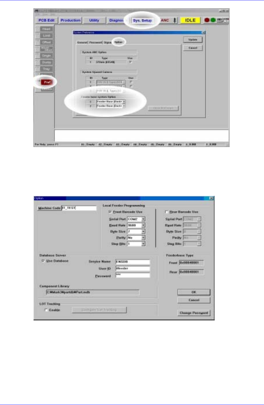
Specify the setting following the order of [Sys.Setup Pref. Option Feeder base
system Option] as shown in [Figure1-1].
For example, if the IFS with a Docking Cart on the front feeder lane is applied, set the
item ‘1’ to ‘Feeder Base [Dock+IQ]’. [Figure 1-1] shows the setting for the case where the
IFS with Docking Carts on both front (‘1’) and back (‘2’) is applied.
Samsung Intelligent Feeder System
Figure 1-1. System Setup Dialog box for IFS application
1.2.1.2. FIS environment setup
After installing FIS, use System Setup in FIS to set configuration to be compatible with
the equipment. (FIS: Feeder Information Server)
Figure 1-2. FIS environment setup dialog box
The variables in Figure 1-2 and their meanings are illustrated in Table A-1.
1-2

IT Feeder System
1-3
Table 1-1. Setting variables in FIS’s environment setting dialog
Item Description
Machine Code Unique machine code
Feeder
Scanner
Serial Port Serial port for communicating with feeder
scanner hardware
Service Name The service name for accessing the database
User ID The user ID for accessing the database
Database
Server
Password The password for accessing the database
Component
Library
Path and the file name of component library
Barcode Use Whether the front and rear barcode readers
are installed or not
Local Feeder
Programming
Barcode Scanner
Serial Port
Baud Rate
Byte Size
Parity
Stop Bits
Setting for the communication device to
interface with barcode reader
[F] Setting front feeder base type Feeder base
Type
[R] Setting rear feeder base type
Change
Password
Set the password for modifying the
environment variables
1.2.2. Installation path and file structure
The installation paths can be changed by the user. (The following is based on the
assumption that the Mark3 path is C:\Mark3)
Program location
C:\Mark5\Bin\Mark5.exe
C: \Mark5 \Bin \FdInfoSrv320.exe
\Oradb.dll
\MFCEx.dll
\MFCx1020.dll
\SerialComm.dll
\ThreadBase.dll
Component Library location
C:\Mark5\PartDB\UPD.mdb
1.3. MMI Add-On Functions in IT Feeder System
1.3.1. Toolbar
The SM320 MMI S/W for IFS provides Toolbar buttons for IFS manipulation as shown in
[Figure 1-3] for the convenience of use. The functions of these buttons are as follows.