IT Feeder Manual-SM320(English V2.0)Ver1 - 第15页
IT Feeder System 1-3 T able 1-1. Setting variables in FIS ’ s envir onment setting dialog Item Description Machine Code Unique machine co de Feeder Scanner Serial Port Serial port for communicating with feeder scanner ha…
Samsung Intelligent Feeder System
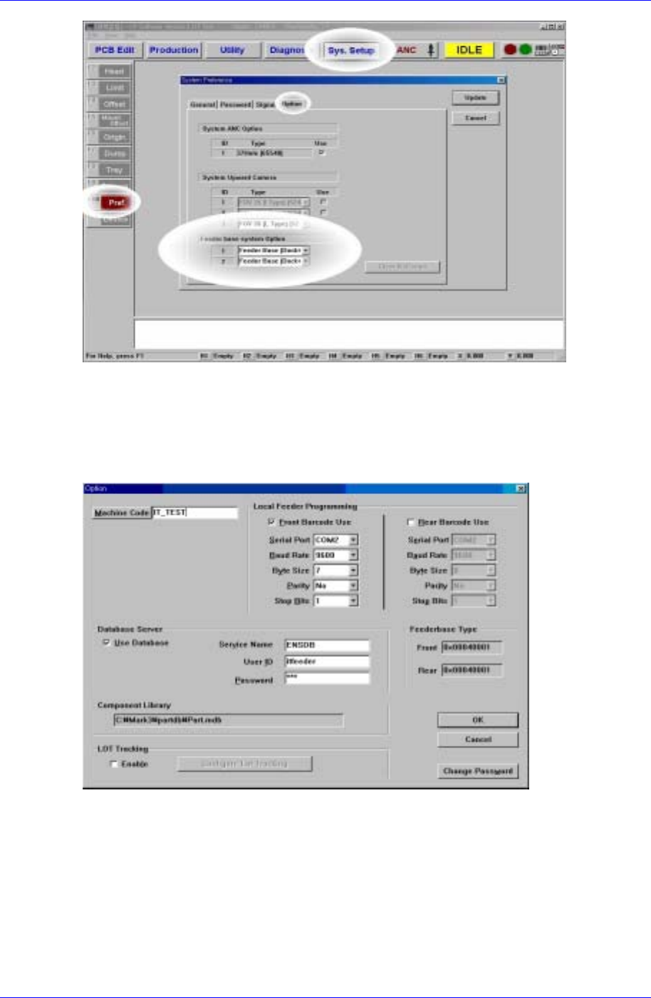
Figure 1-1. System Setup Dialog box for IFS application
1.2.1.2. FIS environment setup
After installing FIS, use System Setup in FIS to set configuration to be compatible with
the equipment. (FIS: Feeder Information Server)
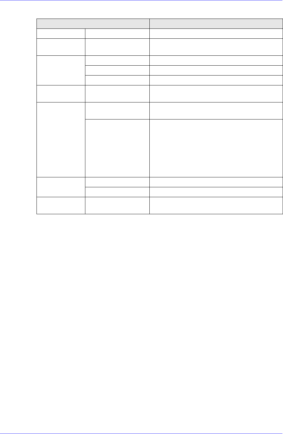
Figure 1-2. FIS environment setup dialog box
The variables in Figure 1-2 and their meanings are illustrated in Table A-1.
1-2
IT Feeder System
1-3
Table 1-1. Setting variables in FIS’s environment setting dialog
Item Description
Machine Code Unique machine code
Feeder
Scanner
Serial Port Serial port for communicating with feeder
scanner hardware
Service Name The service name for accessing the database
User ID The user ID for accessing the database
Database
Server
Password The password for accessing the database
Component
Library
Path and the file name of component library
Barcode Use Whether the front and rear barcode readers
are installed or not
Local Feeder
Programming
Barcode Scanner
Serial Port
Baud Rate
Byte Size
Parity
Stop Bits
Setting for the communication device to
interface with barcode reader
[F] Setting front feeder base type Feeder base
Type
[R] Setting rear feeder base type
Change
Password
Set the password for modifying the
environment variables
1.2.2. Installation path and file structure
The installation paths can be changed by the user. (The following is based on the
assumption that the Mark3 path is C:\Mark3)
Program location
C:\Mark5\Bin\Mark5.exe
C: \Mark5 \Bin \FdInfoSrv320.exe
\Oradb.dll
\MFCEx.dll
\MFCx1020.dll
\SerialComm.dll
\ThreadBase.dll
Component Library location
C:\Mark5\PartDB\UPD.mdb
1.3. MMI Add-On Functions in IT Feeder System
1.3.1. Toolbar
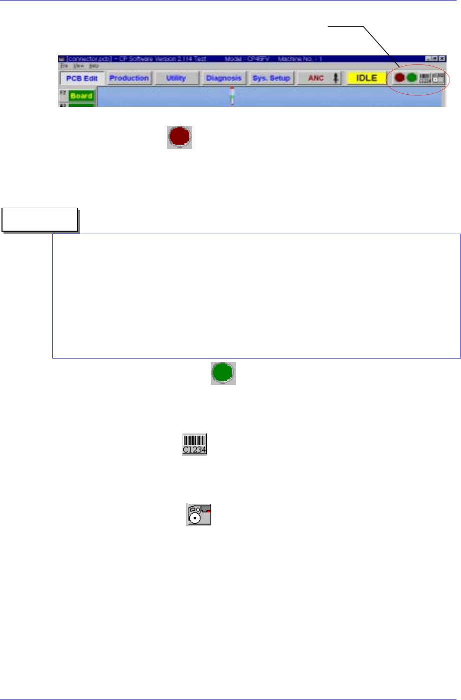
The SM320 MMI S/W for IFS provides Toolbar buttons for IFS manipulation as shown in
[Figure 1-3] for the convenience of use. The functions of these buttons are as follows.
Samsung Intelligent Feeder System
FIS Toolbar Menu
Figure 1-3. Mark5 MMI Toolbar
Feeder Error Status
Displays the Feeder error status. The red icon flashes when there is a feeder error.
When the feeder error status is clicked regardless of the error status, the Feeder Error
Dialog box is displayed.
There are two types of Feeder errors; mismatch error and empty error. The error message
is displayed without differentiating which error it is. All errors are based on the PCB
program currently downloaded in the equipment.
Reference
The mismatch error is the case where there is a mismatch between the feeder type and
part name in the downloaded PCB program and the actual feeder type and part name
installed in the equipment.
‘Empty Error’ means that the feeder is not properly mounted in the machine although the
use of a feeder is registered in the PCB program. In such instance the machine does not
operate.
Part Shortage Warning Status
The green icon flashes when the part count of a feeder in use drops below the set part
count. Like the feeder error, when this status is clicked regardless of the current
warning status, the Part Shortage warning dialog box is displayed.
Manual Barcode Entry
If barcodes can not be read due to damaged barcodes or malfunction of the barcode
reader, click this button to display the manual barcode input dialog box. Click with
the mouse or use numeric keys to enter barcodes.
View FIS main window
Starts the FIS main window that shows feeder information in the PCB program and
actual feeder information.
1.3.2. Automatic Feeder Creation in PCB Edit
If the IFS is used there is a <Create> button that creates the feeder in the “Feeders” dialog
box of the SM320 MMI. When the ‘Create’ button is pressed, the information on the
feeder being installed on the feeder base is automatically registered in the ‘PCB’ file in
operation. In this case, the feeder information already registered in the ‘PCB” file is
deleted.
1-4