IT Feeder Manual-SM320(English V2.0)Ver1 - 第19页
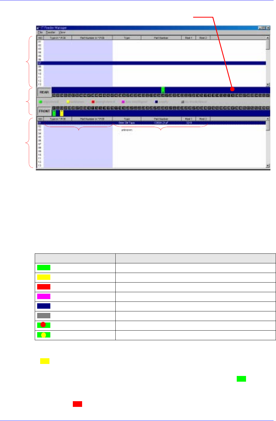
IT Feeder System 1-7 Front feederbase Rear feederbase statu s des cripti on Programm ed feeder & p art Actu al feeder & p art Feed er status Figur e 1-7. FIS main window 1.4.1.1. Feeder S tatus Displays real time…
Samsung Intelligent Feeder System
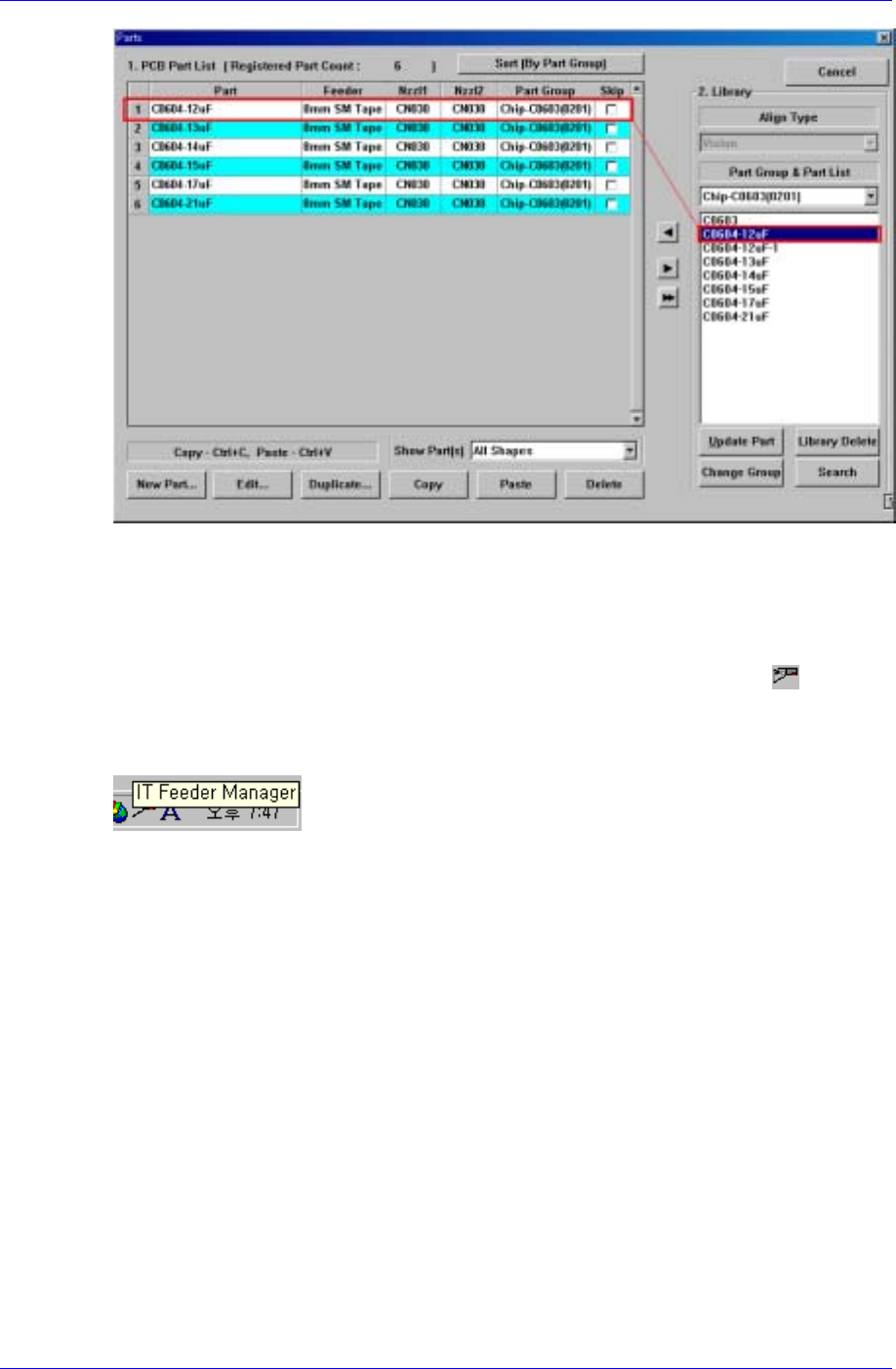
Figure 1-5. Part library addition
1.4. Feeder Information Server (FIS)
When Mark3 MMI is started and FIS is executed normally, the FIS icon ( ) appears
in the System Tray of Windows as shown in [Figure 1-6]. When the mouse pointer is
located on this icon, a tool tip describing “Feeder Scanner Controller” is displayed as
shown in the figure.
Figure 1-6. Windows System Tray and FIS Icon
FIS consists of one main window and several status dialog boxs. All manipulation is
carried out by the MMI Toolbar buttons.
1.4.1. FIS main window
The FIS main window displays the PCB program currently loaded in the equipment, the
feeder array and component to be mounted in the feeder in the program, types of feeders
installed in the actual equipment and their part counts. The screen structure is shown in
[Figure 1-7].
The FIS main window is not displayed unless a certain manipulation is taken by the user.
Execute Display FIS Main Window to view the feeder in the PCB program downloaded
in the equipment, ID of the feeder mounted on the actual equipment, and other
information. There are two ways to view the FIS main window. Firstly, pressing the
right most button on the FIS Toolbar menu of Mark5 MMI Toolbar in [Figure 1-3]
displays the FIS main window.
Secondly, double click on the left button of the mouse on the FIS icon from System Tray
in [Figure 1-6].
1-6
IT Feeder System
1-7
Front
feederbase
Rear
feederbase
status
description
Programmed
feeder & part
Actual
feeder & part
Feeder status
Figure 1-7. FIS main window
1.4.1.1. Feeder Status
Displays real time information on the feeder currently installed on the feeder base. The
statuses of front and rear feeder bases are displayed separately in the upper and lower part
of the screen. The feeder status is indicated by the color and width. The width displayed is
in proportion to the actual feeder width and the meaning of each color is illustrated in
[Table 1-2].
Table 1-2. Feeder Status
Color Description
Green Intelligent feeder
Yellow Unknown feeder
Red Intelligent feeder unregistered in database
Magenta Non-intelligent feeder
Dark blue Empty feeder slot
Dark gray Non-intelligent feeder base or docked-out
Red blinking In case the ‘Mismatch Error’ occurs
Yellow blinking In case the ‘Shortage Warning’ occurs
When a Feeder is installed on the feeder base, the respective slot appears as unknown
(
) . This means the Feeder Scanner has sensed the newly installed Feeder.
When the Feeder scanner reads the feeder ID normally, the database is searched. If there
is a feeder with the respective ID, the feeder status changes to intelligent (
) and the
feeder information is displayed in the feeder list.
If there is no feeder with the ID in the database, the feeder status changes to
unregistered(
) and displayed in the feeder list.
Samsung Intelligent Feeder System
When the Feeder sacnner can not read a feeder, the feeder status is displayed as non-
intelligent feeder (
).
An empty feeder slot is indicated as empty(
). If the feeder base is not installed, the
feeder status is displayed as no-feederbase(
).
When the ‘Mismatch Error’ occurs with the feeder installed on the feeder base, it is
indicated as ( ) and the ‘Shortage Warning’ occurs, indicated as ( ) on the screen.
1.4.1.2. Feeder List
Displays information on the feeder programmed in the PCB program and parts, and real
time information on the feeder currently installed on the feeder base. Just like the
Feeder Status, the front feeder base is displayed in the upper part of the screen and the
rear feeder base, lower part of the screen.
Two columns on the left of the list shows data in the PCB program and the four columns
on the right of the list shows the status of actually installed feeder. The information
displayed is as follows.
Feeder type in PCB program
Part name in PCB program
Installed feeder ID
Installed feeder type
Installed part name
Installed part count (Real Time Data)
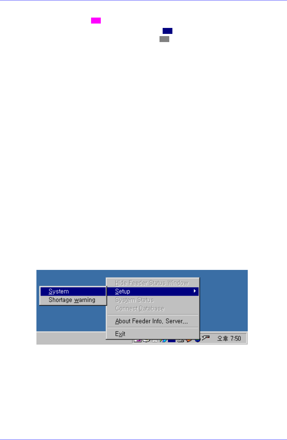
1.4.2. Structure of the File Menu
The menu is selected in two ways: by using the system tray in Windows, or by using the
FIS current status window.
Place the mouse cursor on the FIS icon and right-click the mouse. Then the FIS menu is
displayed as shown in the following figure.
Figure 1-8. FIS Menu in System Tray
1-8