IT Feeder Manual-SM320(English V2.0)Ver1 - 第23页
IT Feeder System 1-1 1 Figur e 1-12. Scr een con figuration after splicing is completed 1.4.3.2. Feeder Info The selected feeder information can be checked . After selecting the feeder to be checked, select <Feeder In…
Samsung Intelligent Feeder System
Figure 1-10. FIS main window menu configuration
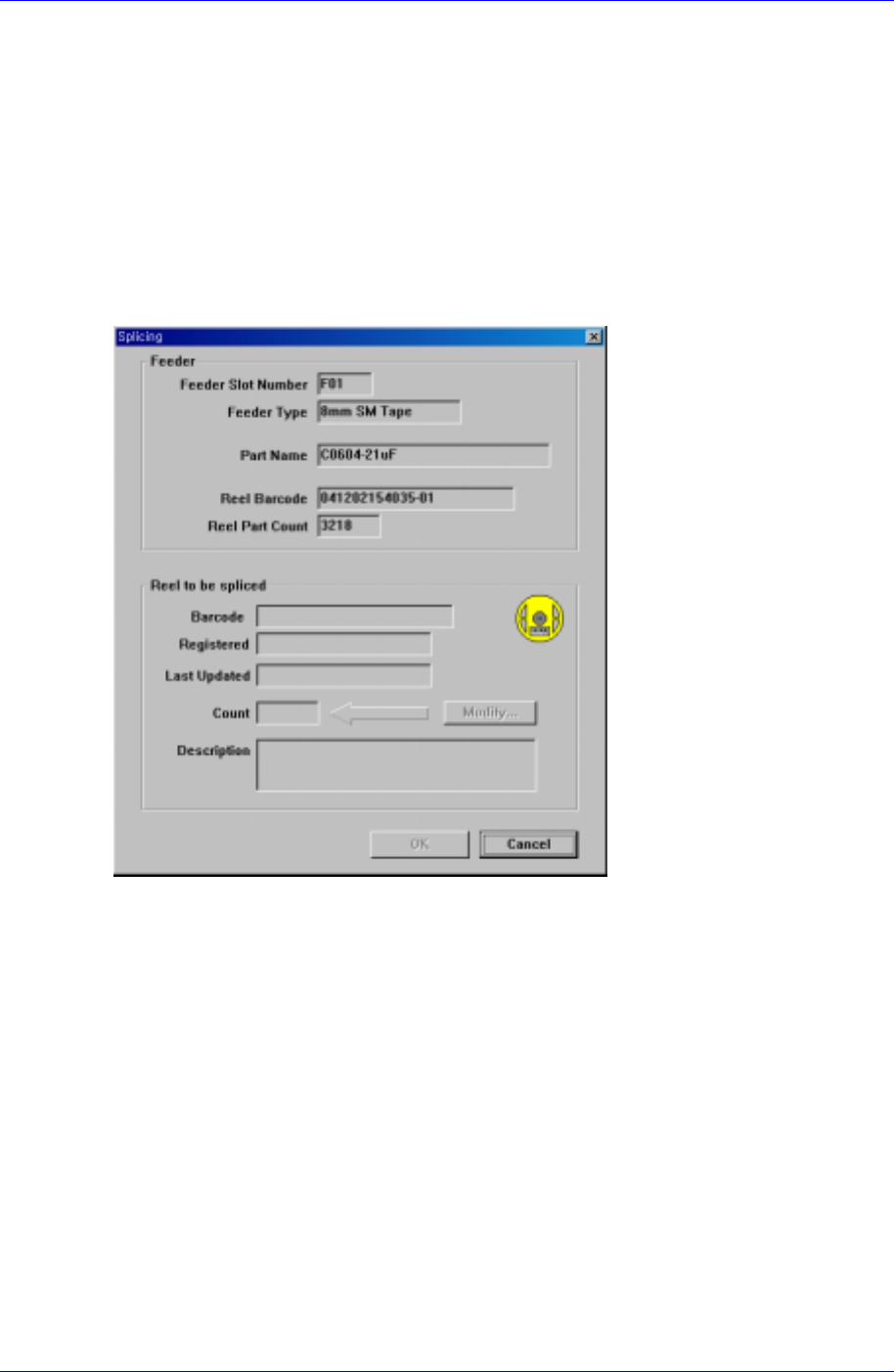
1.4.3.1. Splice reel
Used when the remaining reel quantity on the feeder is small or when other reels
containing identical parts are continuously used.
Select the <Splice reel> by clicking <Splice reel> in the <Feeder> menu or by right
clicking the mouse.
Figure. 1-11 shows the feeder when the contents of the feeder to be spliced are normal.
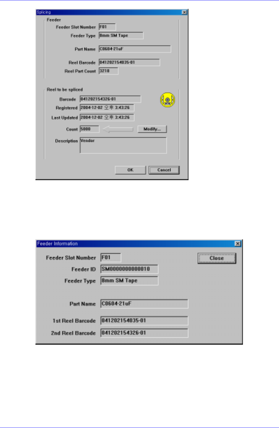
Figure. 1-12 indicates the feeder when the reel (2nd Reel Code) is input through a
barcode.
Figure 1-11. Screen configuration for Feeder→Splicing selection
1-10
IT Feeder System
1-11
Figure 1-12. Screen configuration after splicing is completed
1.4.3.2. Feeder Info
The selected feeder information can be checked. After selecting the feeder to be checked,
select <Feeder Info> in <Feeder>. Then the feeder information can be checked as shown
in the following figure.
Figure 1-13. Feeder information screen configuration
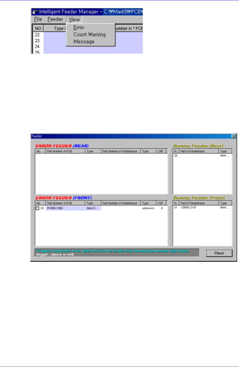
1.4.4. Structure of the View Menu
This is the menu from which error status and remaining quantity warning message are
displayed. Figure. 1-14 shows the menu configuration.
Samsung Intelligent Feeder System
Figure 1-14. FIS main window view menu configuration
1.4.4.1. Error
When the PCB program is downloaded to the equipment, FIS checks the error of the
feeder installed on the feeder base. The feeder array, feeder type, and part name
programmed in the PCB program are compared with the feeder information of currently
installed feeder. If there are any discrepancies, an error message occurs and the operation
stops.
When a feeder error occurs, the dialog box in [Figure 1-15] is displayed automatically,
and the latest error in the list is selected.
Figure 1-15. Feeder error dialog box
The list is displayed separately for the front and rear and the items displayed in the dialog
box are as follows.
Error feeder list
Indicates the contents of the currently occurred error. The first column of the list is
the Feeder column and the next two columns indicate the feeders and parts in the
PCB program. The remaining 3 columns indicate the contents of the feeders actually
mounted. If they are empty, it means that an empty error occurred. If they are filled, it
means that a mismatch error occurred. When a mismatch error occurs, it is
immediately indicated through the lamp and the alarm is sounded. When the Empty
error occurs, it is indicated only through the lamp.
Dummy (or extra) feeder list
1-12