IT Feeder Manual-SM320(English V2.0)Ver1 - 第39页
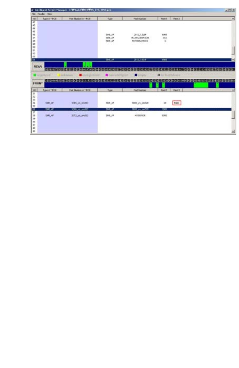
IT Feeder System 1-27 Figur e 1-30. Splicing Completion Indication of IT Feeder Manager
Samsung Intelligent Feeder System
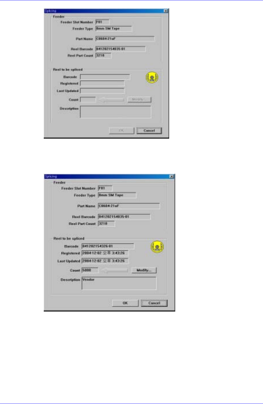
Figure 1-28. Splicing dialog box
Splice the new part reel and read the part reel barcode with the barcode reader. If the
barcode is input successfully, two types of part reel information are displayed in the
screen as shown in Figure. 1-29.
Figure 1-29. Splicing completed screen
< Click the <OK> button to complete the splicing. Then the part reel count applied to
the IT Feeder Manager is indicated.
1-26
IT Feeder System
1-27
Figure 1-30. Splicing Completion Indication of IT Feeder Manager
Samsung Intelligent Feeder System
1.5. SM Type Feeder
1.5.1. Installation of Feeder’s Own Memory
The built-in memory of the SM Feeder includes the feeder information and part reel
information. The information is saved when the feeder base or jig is installed. The
information in the feeder's own memory is updated by comparing it with the information
contained in the data base.
1.5.2. LED Display
The SM feeder has a LED, which indicates the status of feeder usage.
The LED indicates the status of feeder operation and network connection, through which
the user can easily understand the current operation status.
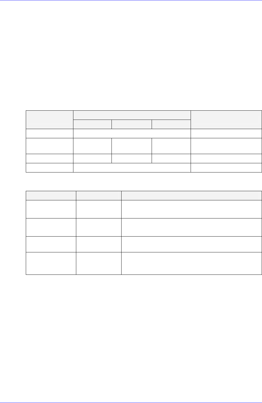
Table 1-4. Feeder Status LED
LED Display
Status
Status 1 Status 2 Status 3
Description
Normal (Ready) Green Waiting for operation
Feeding (Busy) Yellow Green Yellow Change in status during
operation
Warning Yellow Blink Yellow Blink Yellow Blink When warning occurs
Error Red When error occurs
Table 1-5. Network Status LED
Status LED Display Description
On-line,
Not connected
Green Blink
The device is connected but communication with
ITFS is unavailable
On-line,
Connected
Green
The device is connected and communication with
ITFS is available
Connection
Time-out
Red Blink
When it takes a long time for the device to
communicate
Critical
Communication
Failure
Red
Only power is supplied while communication with
ITFS is unavailable
1-28