IT Feeder Manual-SM320(English V2.0)Ver1 - 第40页
Samsung Intelligent Feeder System 1.5. SM T ype Feeder 1.5.1. Installation of Feeder ’ s Own Memory The built-in memory of the SM Feeder incl udes the feeder information and part reel information. The information is save…
IT Feeder System
1-27
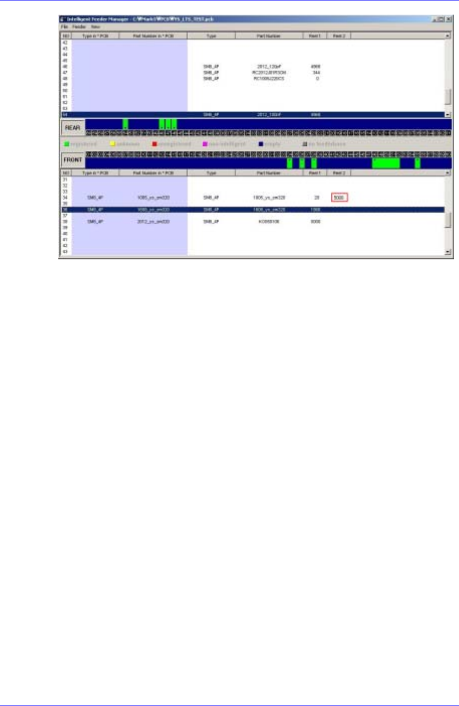
Figure 1-30. Splicing Completion Indication of IT Feeder Manager
Samsung Intelligent Feeder System
1.5. SM Type Feeder
1.5.1. Installation of Feeder’s Own Memory
The built-in memory of the SM Feeder includes the feeder information and part reel
information. The information is saved when the feeder base or jig is installed. The
information in the feeder's own memory is updated by comparing it with the information
contained in the data base.
1.5.2. LED Display
The SM feeder has a LED, which indicates the status of feeder usage.
The LED indicates the status of feeder operation and network connection, through which
the user can easily understand the current operation status.
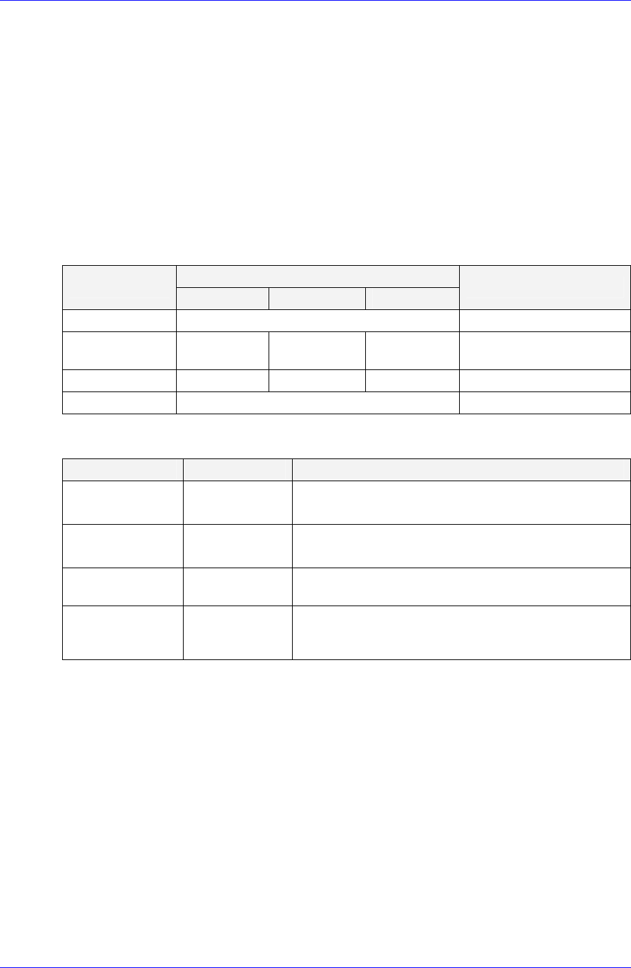
Table 1-4. Feeder Status LED
LED Display
Status
Status 1 Status 2 Status 3
Description
Normal (Ready) Green Waiting for operation
Feeding (Busy) Yellow Green Yellow Change in status during
operation
Warning Yellow Blink Yellow Blink Yellow Blink When warning occurs
Error Red When error occurs
Table 1-5. Network Status LED
Status LED Display Description
On-line,
Not connected
Green Blink
The device is connected but communication with
ITFS is unavailable
On-line,
Connected
Green
The device is connected and communication with
ITFS is available
Connection
Time-out
Red Blink
When it takes a long time for the device to
communicate
Critical
Communication
Failure
Red
Only power is supplied while communication with
ITFS is unavailable
1-28

Part Station
Chapter 2. Part Station
2-1
2.1. Overview
Part Station, a module in IT Feeder Station, is a Windows program that registers
PartReels necessary for Off-Line PCB operations and creates Barcodes by using the
newly created ReelCodes.
This program reads the registered part code in the machine from the database and creates
the Part Reel barcode for the corresponding part. Each station program of the IT feeder
consists of the Oracle DB that is controlled commonly.
Memo
Each part number used in all equipment must be controlled by a unique code. In other
words, once a part is registered, that part should have the same name. Otherwise, it will
be very difficult to control parts consistently. Therefore, at the beginning of system
construction, all workers should bear this in mind. For example, if 1005 Type 100Ohm
resistance is registered as A in SM320, it should be registered as A in other equipment
(CP45FV, CP60, CP40) also. Part registration data (Vision data, Align data, etc) can differ
from equipment to equipment, but one name should be used for all equipment so that Part
Station can always create the ReelCode for 1005 Type 100Ohm resistance as PartName
A.
Part Station always creates unique Reelcodes and duplicated codes are not created. The
purpose is to control parts by the reel. The basic installation directories and file structures
of Part Station are as follows. The user can change the installation directory if desired.
For detailed information on installation method, please refer to “Installation of Part
Station in IQ Feeder Station”.
Program location
C:\Program Files\ITFeeder\PartStation\PartStation.exe
System requirements to run this program are as follows.
CPU: IBM PC compatible Pentium over 266Mhz (Pentium 333MHz or higher
processor is recommended)
OS: Over Microsoft Windows 2000
Memory: Over 128MB (over 256MB is recommended)
Hard Disk: 2MB hard disk space (need to secure at least 2GB of free hard disk
space)
The Part Station system consists of the Part Station program, Oracle Database Client,
waste Reel.bak for backup files, and Recycle.dat. The operation of Feeder Station and IQ
Module of the equipment is interrelated.