IT Feeder Manual-SM320(English V2.0)Ver1 - 第43页
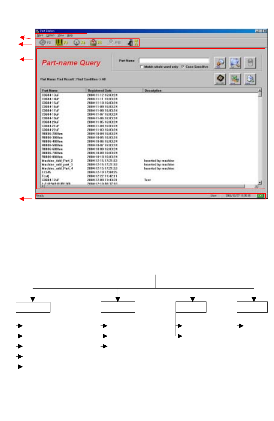
Part S tation 2-3 Status bar User change, current time and DB c onnection status are indicated here. Main menu T oolbar Execution window Sta tu s B ar Figur e 2-1. S tructur e of the main scr een 2.2. Structure of the …
Samsung Intelligent Feeder System
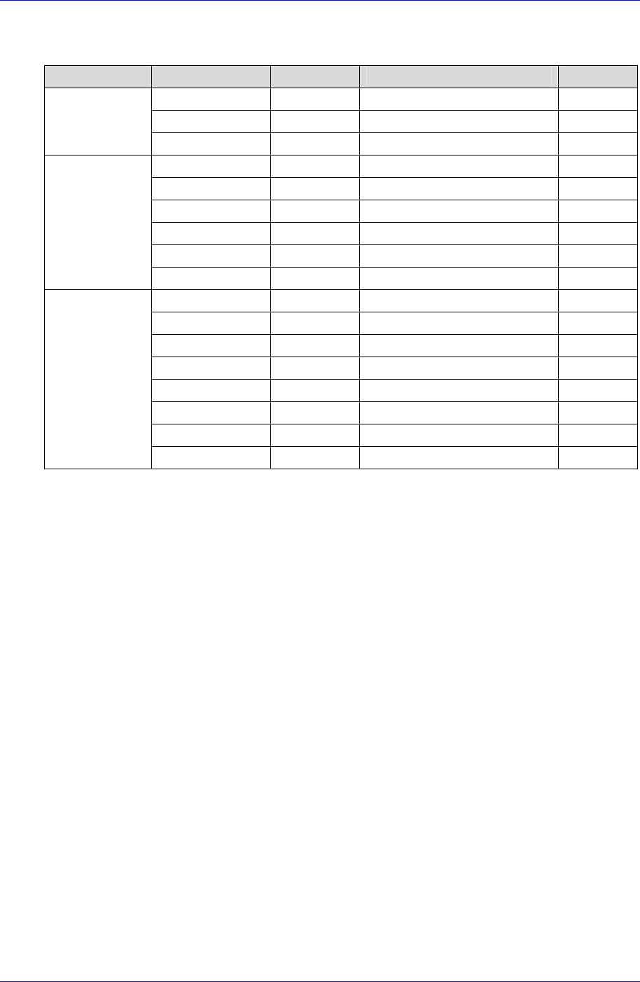
The Data controlled by Part Station is as follows.
Table 2-1. DB data for managing the IQ Feeder
Classification Code Type/size Item Note
BOMCODE Text / 24 (PartName)
INS_DATE Date Date of registration
BOM
Data
DESC Text / 50 Description
REELCODE Text / 20 Part Reel Code
BOMCODE Text / 24 (PartName)
COUNT Num / Long Number of parts
INS_DATE Date ReelCode registration date
UPD_DATE Date Reel data update date
PartReel data
DESC Text / 50 Description
FEEDER_ID Text / 10 Feeder RF-ID
FEEDER_TYPE Num / Int Feeder Type
REELCODE Text / 20 Part Reel Code
MC_CODE Text / 20 Equipment in use
CART_ID Text / 10 CART ID in use
INS_DATE Date Feeder registration date
UPD_DATE Date Feeder data update date
Feeder data
DESC Text / 50 Description
2.1.1. Configuration Of System Screen
The system screen consists of the following.
Main menu
Consists of Work, Option, View, and Help. Detailed information on each menu will
be provided later.
Toolbar
Located under the Main menu. It consists of 6 icons. Each icon has respective
keyboard shortcut. When a menu is executed, the respective icon turns grey and it is
disabled. When another menu is executed, it is enabled again. When the mouse
pointer is located on a menu, respective tool tip appears, giving a brief description of
the menu.
Execution window
This is where the task is actually carried out. The results of various queries and
registration and other commands are displayed here.
2-2
Part Station
2-3
Status bar
User change, current time and DB connection status are indicated here.
Main menu
Toolbar
Execution
window
Status Bar
Figure 2-1. Structure of the main screen
2.2. Structure of the Main Menu
The structure of the Main Menu for Part Station is as follows.
P
art
S
tat
i
on
Ver 2.0
Figure 2-2.IT Feeder Part Station Main Menu Tree
About IT Feeder
State
Toolbar
Connect Database (F12)
User Change (F11)
Configuration (F10)
Exit
Waste Part Reel (F5)
Part Reel Management (F4)
Part Reel Registration (F3)
Part Information (F2)
Help
View Option
Work
2.2.1. Work
Part Information
Searches or deletes the PartNames registered in the equipment.

Samsung Intelligent Feeder System
Part Reel Registration
Registers new Part Reels and creates bar codes.
Part Reel Management
Searches registered ReelCodes with various conditions, deletes reels, or changes the
number of remaining parts.
Waste Part Reel
Deletes used up PartReels.
Exit
Ends a job.
2.2.2. Option
Configuration
Can input the database login information and also designate the barcode scanner type.
Enables to change the password for the SuperUser (management).
User Change
Can change the user mode. Two types of user modes are available: regular mode and
SuperUser mode. The SuperUser mode requires a password for the control of use.
Connect Database
Reconnects the database when it is disconnected.
2.2.3. View
Toolbar
Displays or restores the Toolbar at the top of the screen.
Status Bar
Remove or restore the status bar at the bottom of the screen.
2.2.4. Help
About IT Feeder: Displays program information.
2-4