IT Feeder Manual-SM320(English V2.0)Ver1 - 第75页
Feeder S t ation Figur e 3-4. Feeder Info. scr een Description of the screen Configuration of Find mark at the upper left and m ode change button at the bottom right. Consists of 3 modes; Find, Install, and Uninsta…
Samsung Intelligent Feeder System
communication port. Also the interval for Database Sync can be set.
Connect Database
When connection with the database is disconnected, attempt connection once again.
3.2.3. Help
About Feeder Station: Shows the information on the program.
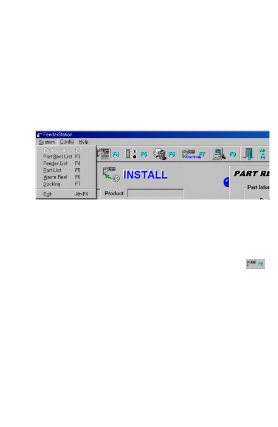
3.3. System menu
When the System menu is selected on the Main menu bar, the following submenus appear.
The System menu consists 6 submenus; Feeder Info, Part Reel List, Feeder List, Part List,
Waste Reel, and Exit.
Figure 3-3. System submenus
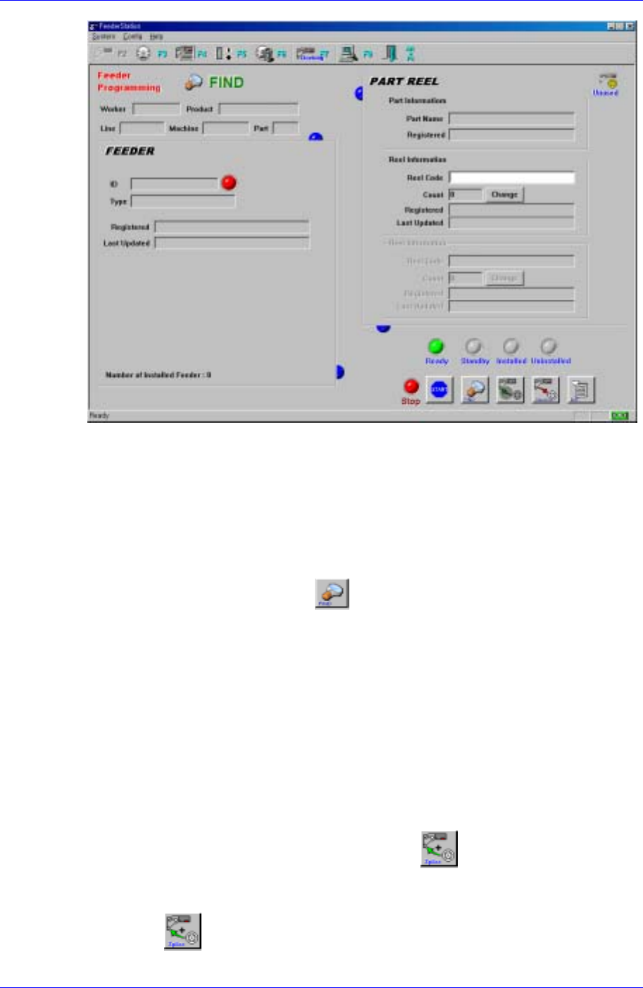
3.3.1. Feeder Info.[F2]
Feeder Info. enters whether the PartReel registered in the Part Station is installed in the
Feeder or not. The PartReel registered in the Feeder or the Feeder in which the PartReel is
installed can be searched.
To execute it, select Feeder Info. from the Main menu or the tool bar, select
, or
press the [F2] key.
3-4
Feeder Station
Figure 3-4. Feeder Info. screen
Description of the screen
Configuration of Find mark at the upper left and mode change button at the
bottom right.
Consists of 3 modes; Find, Install, and Uninstall.
Find Mode:
Simple search mode. Searches whether the Feeder or the Part Reel is
installed. When the button is pressed, the mode is changed to the
Find Mode.
If the feeder ID is read using the RF-ID Reader or if the barcode is read,
the status of the feeder and part stored in the database are indicated.
If the installed feeder ID or part reel barcode is read, the information on
the feeder and part reel is indicated on the screen and the ring shaped
connecting mark is indicated between these pieces of information.
If the non-installed feeder ID or part reel barcode is read, only the
corresponding information is indicated and the connecting link is not
indicated.
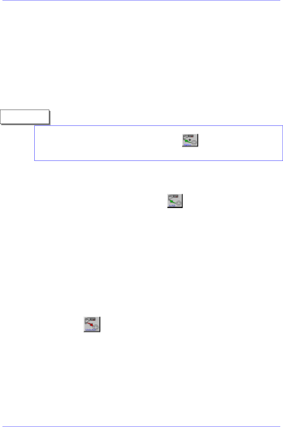
Splicing function
After inquiring after the part reel that is not installed in the feeder, two
part reels can be connected using the
button.
How to attach:
1) If the part reel information is read, it is indicated on the screen.
2)
button is enabled. Then click the button.
3-5
Samsung Intelligent Feeder System
3) The perviously inputted part reel information moves down to the lower side
of the screen and the screen changes to the state waiting for the second part
reel.
4) Read the barcode of the second part reel to be spliced.
5) The two different part reels are connected and displayed on the screen. The
user then physically connects the part reel.
How to detach:
1) If the part reel barcode is read, the part reel information is indicated on the
screen.
2) In the event of a spliced barcode, the Cancel button becomes enabled.
3) If the Cancel button is clicked, then the splicing is disconnected
The splicing function is available only in the Find mode. The number of part reels that
can be spliced is two. When the reels are spliced, the button is disabled.
Reference
※ In order to install the part reel in the feeder, the 2
nd
part reel barcode must be read.
Install Mode: The mode to install the Part Reel in the Feeder. Installation is
possible only when an operation has been started. When the operation data is
entered after pressing the start button (Figure 3-8), the mode changes to the
Install Mode. To return to the Install Mode after a mode change during an
operation, press the Install button
to return to the Install Mode, then
install the Part Reel in the Feeder.
How to install:
1) First, read the feeder ID with the RF-ID Reader to indicate feeder
information in the screen.
2) Install the part reel in the feeder and read the barcode of the
corresponding part reel. In the case of an effective barcode, the
information is indicated in the screen and the connection rings are
created between the feeder and part reel.
3) Installation of the part reel in the feeder is completed.
Attempting to read a previously installed feeder will generate the
message that it has previously been installed.
Uninstall Mode: The mode to remove the Reel installed in the Feeder. Press
the button to use it. In the Uninstall Mode, if the SM feeder is
mounted in the feeder base jig or the barcode is read, it is removed
immediately.
Operation status display on the lower right (Figure 3-7)
Ready: When the Ready status turns green, it is ready for an operation. When
a Feeder ID or Reel Code is entered in the Find or Uninstall Mode, the result
is displayed immediately, but in the Install Mode, it shows the Feeder ID
input standby status.
Standby: The standby status works only in the Install Mode. When a Feeder
ID is entered, it turns green and becomes the Reel Code input standby status.
3-6