3OM-1345-006_w.pdf - 第264页
6-33 AKHEDT -ID 2.1.14 Nozzle Inclination Offset When the "Head" tab is pressed in the "Device Offset" tab sheet and the "Noz. Incln" tab is selected, the following tab sheet appears. Fig. 3…
6-32
AKHEDT-ID
2.1.13 Head Inclination Offset
When the "Head" tab is pressed in the "Device Offset" tab sheet and the "Hd.
Incln" tab is selected, the following tab sheet appears.
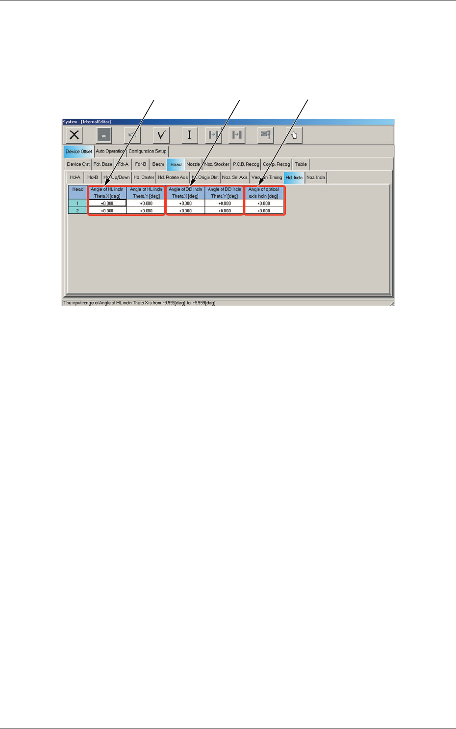
[1] [2]
[3]
Fig. 3F25-2 "Head Incln" Tab Sheet
Head 1 and Head 2
[1] Angle of HL incln Theta X [deg], Theta Y [deg]
The set parameter is used to correct the deviations in the X and Y
direction that will be caused while the HL-axis is moving down if the
axis is tilted.
[2] Angle of DD incln Theta X [deg], Theta Y [deg]
The set parameter is used to correct the deviations in the X and Y
direction that will be caused while the HL-axis is moving down if the
DD-axis is tilted.
[3] Angle of optical axis incln [deg]
The set parameter is used to correct the angle of the component
recognition camera shot.
2.1 Device Offset Data
0609-002
6-33
AKHEDT-ID
2.1.14 Nozzle Inclination Offset
When the "Head" tab is pressed in the "Device Offset" tab sheet and the
"Noz. Incln" tab is selected, the following tab sheet appears.
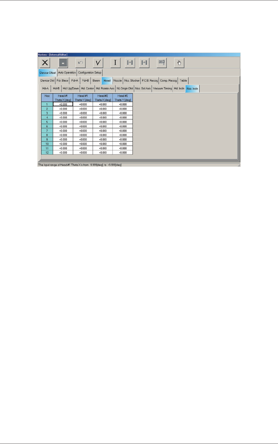
Fig. 3F25-3 "Noz. Incln" Tab Sheet
Nozzles 1 through 12
Head #1 and Head #2
Theta X [deg], Theta Y [deg]
These offsets are used to correct the deviations in the X and Y directions
that will be caused due to the inclination of the nozzle shaft while the
NL-axis is moving down.
2.1 Device Offset Data
0609-002

6-34
AKHEDT-ID
Intentionally Blank
2.1 Device Offset Data
0609-003