EUS0153210_YFact_Standard_E.pdf - 第166页
3-46 3 Board Editor 2 Change the mount position. 1. After selecting the component whose position you want to change, click the [Change Mount Position] button on the toolbar or select "Chang e Mount Position" fr…
3-45
3
Board Editor
3.3 Editing the graphic view
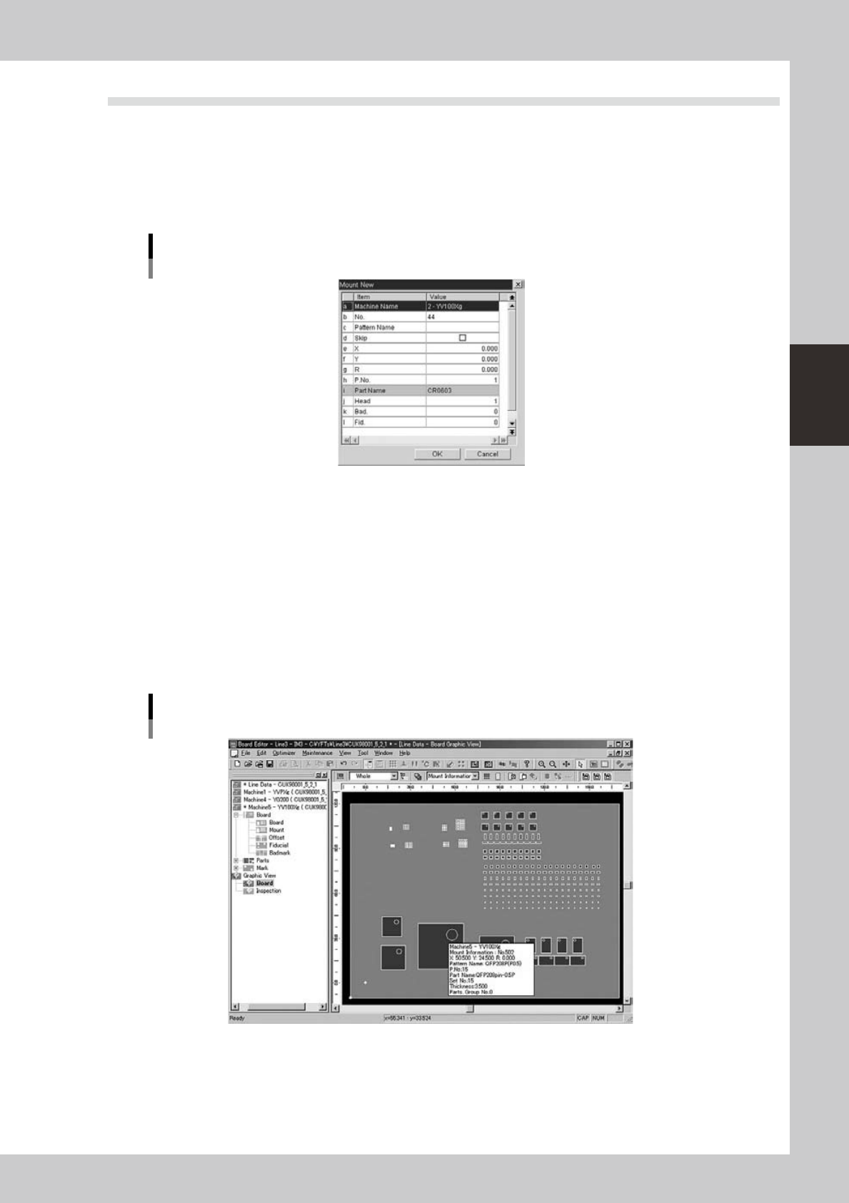
3.3.1 Crating new mount information
The graphic view allows you to create new mount information.
Todothis,clickthe[CreateNewMountInfo]buttonorselect“MountNew”fromthecontextmenuthat
appears by clicking the right mouse button.
Enterthenecessaryparametersandclickthe[OK]button.
Dialog box for creating new mount information
64354-S0-00
3.3.2 Changing the mount positions
Component mount positions can be changed on the graphic view.
1
Select the component whose mount position should be changed.
1. Using the [Move] button, [Select] button and [Zoom] button, find the component whose mount
position you want to change.
When you rest the cursor over the component, a screen tip appears showing the component No.,
mount position, component name, etc.
2. When you find the target component, click to select it. The color of the selected component
changes.
Selecting the component while referring to the screen tip
64355-S0-00
3-46
3
Board Editor
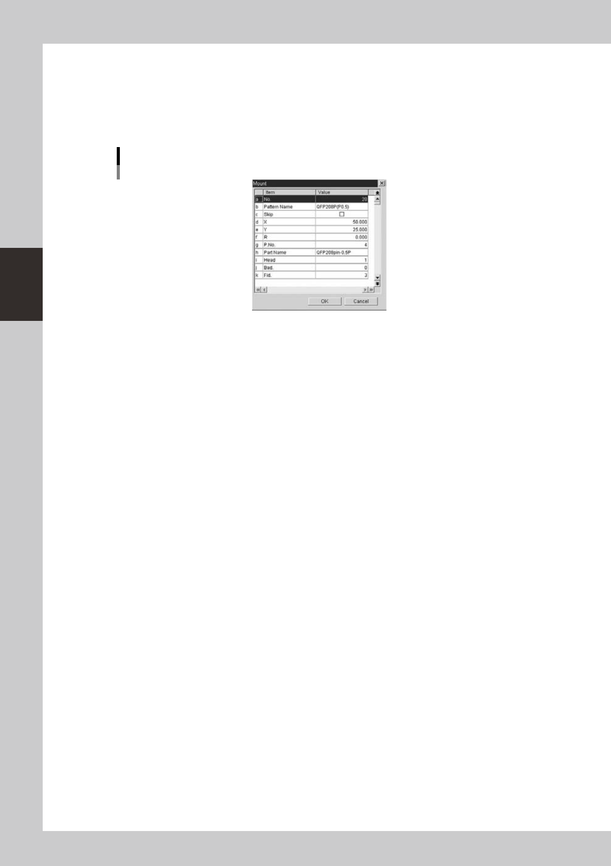
2
Change the mount position.
1. After selecting the component whose position you want to change, click the [Change Mount
Position] button on the toolbar or select "Change Mount Position" from the context menu that
appears by clicking the right mouse button. The “Mount” dialog appears.
2. Change the mount position data in the dialog box and click the [OK] button.
The selected component moves to the specified position.
Dialog box for creating new mount information
64356-S0-00
3-47
3
Board Editor
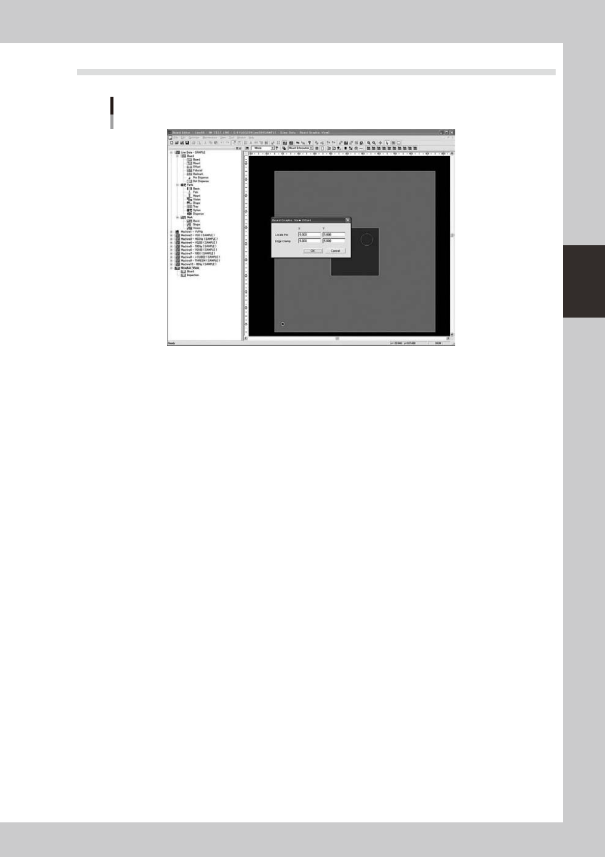
3.4 Board Graphic View Offset setting
Board Graphic View Offset setting
64370-S0-00
Setting for changing the indication point of the origin coordinate (0, 0) from the “position (X = 5 mm, Y = 5
mm) from the board outline” to a desired location.