EUS0153210_YFact_Standard_E.pdf - 第67页
2-33 2 Board Explorer ● Other par ts For the other parts as BGA, inspection step is set 1.1 times bigger than the parts size (maximum margin is 0..5mm for each side) as below. X ( mm ) Y ( mm ) Other parts ( except chip …
2-32
2
Board Explorer
●
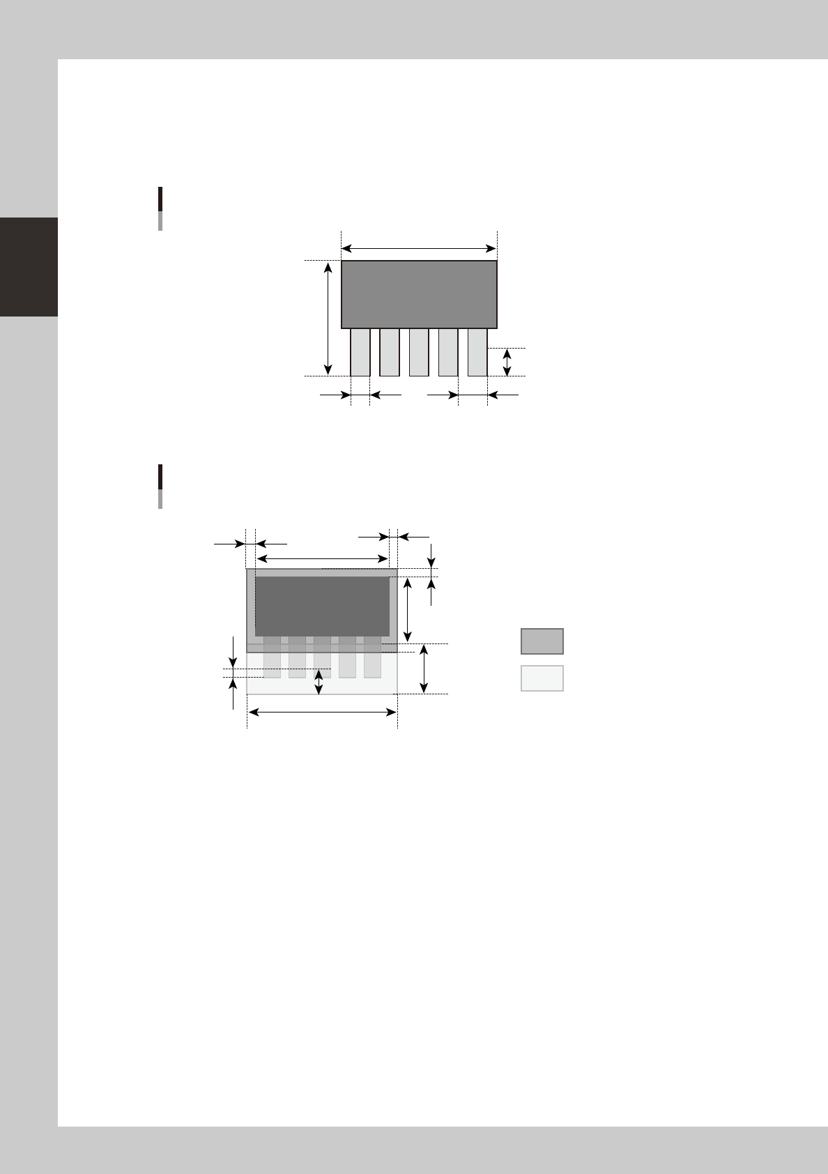
Lead parts
Whenaboarddataofmounterincludeleadpartsasbelow,theconvertedinspectiondatahas,foreachparts,1stepfor
body inspection and 1 step for each lead side to check leads.
Soifapartshasleadsforall4sides,theconvertedinspectiondatahas1bodyinspectionstepand4leadinspection
steps, total 5 steps.
Reflect lead length S mm
Lead pitch U mmLead width T mm
X (mm)
Y (mm)
Lead parts
63201-S0-00
Parts body inspection step
Lead inspection step
VADMIC inspection data of lead parts
Y−S
S x 2.5
(V-1) x U + T + 0.2
S/2
S x 1.25
(Y−S) x 0.05
X x 0.05
X
X x 0.05
63202-S0-00
The inspection steps for body inspection are only set to no lead size as enlarged the size 0.05times (maximum 0.5mm).
But, for the special lead parts, it is set as below “Other parts”.

2-33
2
Board Explorer
●
Other parts
For the other parts as BGA, inspection step is set 1.1 times bigger than the parts size (maximum margin is 0..5mm for
each side) as below.
X (mm)
Y (mm)
Other parts ( except chip and lead parts)
63203-S0-00
Y *1.1
X *1.1
VADMIC inspection data of other parts
63204-S0-00
For each inspection step, by the data conversion, the default data is set as below.
•InspectionStatus :VADMIC
•ReferenceNumber :Patternnameofmounterboarddata
•PartsName :Partsnameofmounterboarddata
•Lib-partsName :Partsnamewhichissetinthecorrespondencetable
•MountblockNo :Blocknumberofmounterboarddata
•Angle :Mountangleofmounterboarddata
•MinimumSizeX,Y:12(bodyinspection),6(solderorleadinspection)
•MinimumArea :25
•MatchingRatio :30
•DivideNumberX :PartsbodysizeX/300μm
•DivideNumberY :PartsbodysizeY/300μm
•LightingType :M(bodyinspection),
L-U(solderinspection),
BR2(leadinspection)
2-34
2
Board Explorer
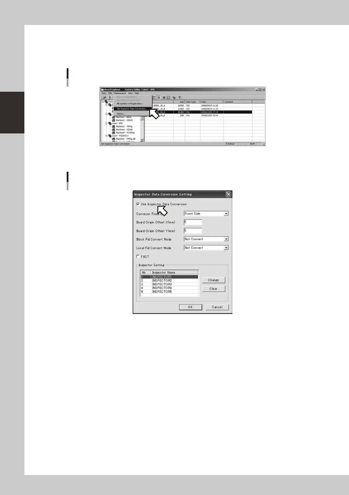
4.2.4 How to set up
1
Select “Inspection program conversion setting” from the “maintenance menu” of
the board explorer.
Selecting [Inspector data conversion setting]
642C2-S0-00
2
Turn on [Use Inspection program conversion].
[Use inspector data conversion] is turned on
642C3-S0-10