sh030106u.pdf - 第100页
3. SIG NALS A ND WIRI NG 3 - 23 You can a lso use a ferru le to conn ect wit h the con nector s. When us ing a ferru le, s elect a ferru le and crimping t ool l isted in t he ta ble be low. Servo amplifi er Wire s ize Fe…
3. SIGNALS AND WIRING
3 - 22
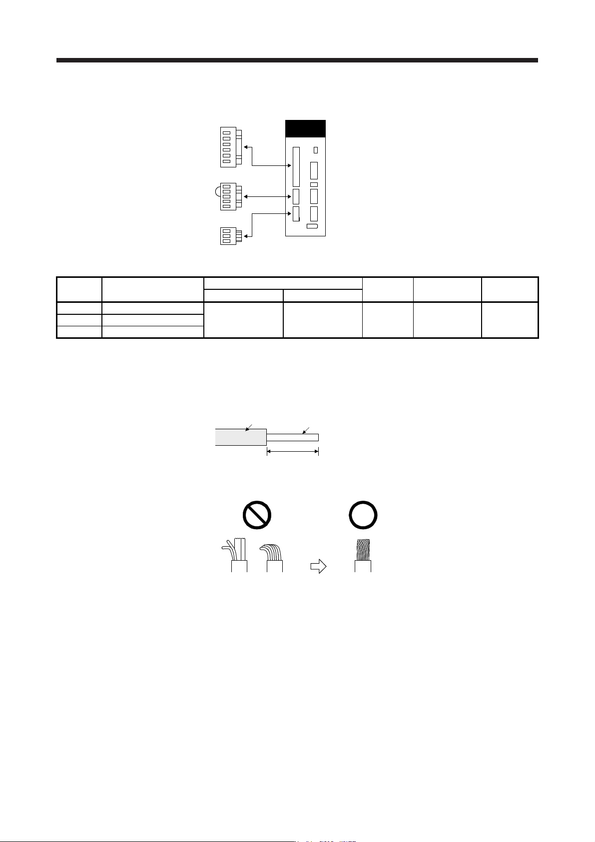
(d) MR-J4-10B1(-RJ) to MR-J4-40B1(-RJ)
CNP2
CNP1
CNP3
Servo amplifier
Table 3.4 Connector and applicable wire
Connector Receptacle assembly
Applicable wire
Stripped
length [mm]
Open tool Manufacturer
Size Insulator OD
CNP1 06JFAT-SAXGDK-H7.5
AWG 18 to 14 3.9 mm or shorter 9
J-FAT-OT (N)
or
J-FAT-OT
JST
CNP2 05JFAT-SAXGDK-H5.0
CNP3 03JFAT-SAXGDK-H7.5
(2) Cable connection procedure
(a) Fabrication on cable insulator
Refer to table 3.1 to 3.4 for stripped length of cable insulator. The appropriate stripped length of
cables depends on their type, etc. Set the length considering their status.
Insulator
Core
Stripped length
Twist strands lightly and straighten them as follows.
Loose and bent strands Twist and straighten
the strands.
3. SIGNALS AND WIRING
3 - 23
You can also use a ferrule to connect with the connectors. When using a ferrule, select a ferrule and
crimping tool listed in the table below.
Servo amplifier Wire size
Ferrule model (Phoenix Contact)
Crimping tool
(Phoenix Contact)
For one For two
MR-J4-10B(-RJ) to
MR-J4-100B(-RJ)
AWG 16 AI1.5-10BK AI-TWIN2×1.5-10BK
CRIMPFOX-ZA3
AWG 14 AI2.5-10BU
MR-J4-200B(-RJ) to
MR-J4-350B(-RJ)
AWG 16 AI1.5-10BK AI-TWIN2×1.5-10BK
AWG 14 AI2.5-10BU AI-TWIN2×2.5-10BU
AWG 12 AI4-10GY
MR-J4-60B4(-RJ) to
MR-J4-350B4(-RJ)
AWG 16 AI1.5-10BK AI-TWIN2×1.5-10BK
AWG 14 AI2.5-10BU
MR-J4-10B1(-RJ) to
MR-J4-40B1(-RJ)
AWG 16 AI1.5-10BK AI-TWIN2×1.5-10BK
AWG 14 AI2.5-10BU
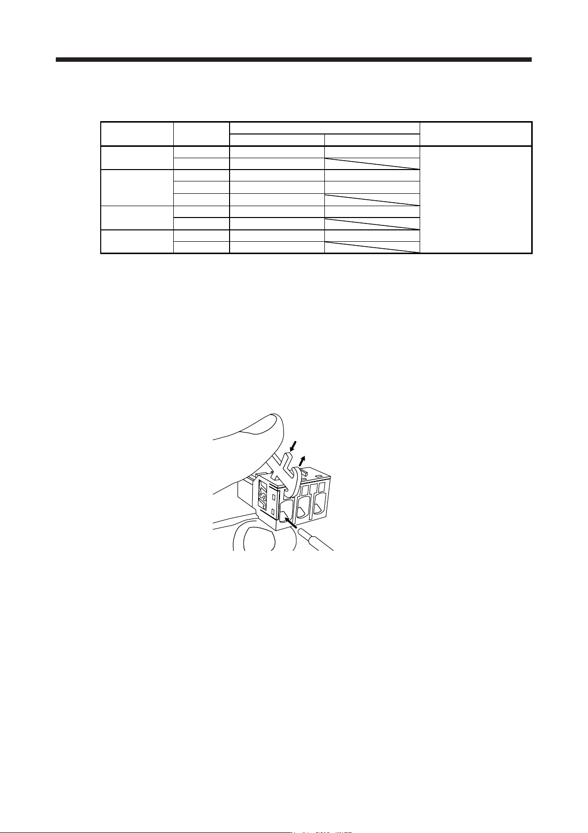
(b) Inserting wire
Insert only one wire or ferrule to each wire insertion hole.
Insert the open tool as follows and push it down to open the spring. While the open tool is pushed
down, insert the stripped wire into the wire insertion hole. Check the wire insertion depth, and make
sure that the cable insulator will not be caught by the spring and that the conductive part of the
stripped wire will not be exposed.
Release the open tool to fix the wire. Pull the wire lightly to confirm that the wire is surely connected.
In addition, make sure that no conductor wire sticks out of the connector.
The following shows a connection example of the CNP3 connector for MR-J4-200B(-RJ) and MR-J4-
350B(-RJ).
1) Push down the open tool.
3) Release the open tool to fix the wire.
2) Insert the wire.
3. SIGNALS AND WIRING
3 - 24
3.4 Connectors and pin assignment
POINT
The pin assignment of the connectors is as viewed from the cable connector
wiring section.
For the STO I/O signal connector (CN8), refer to chapter 13.
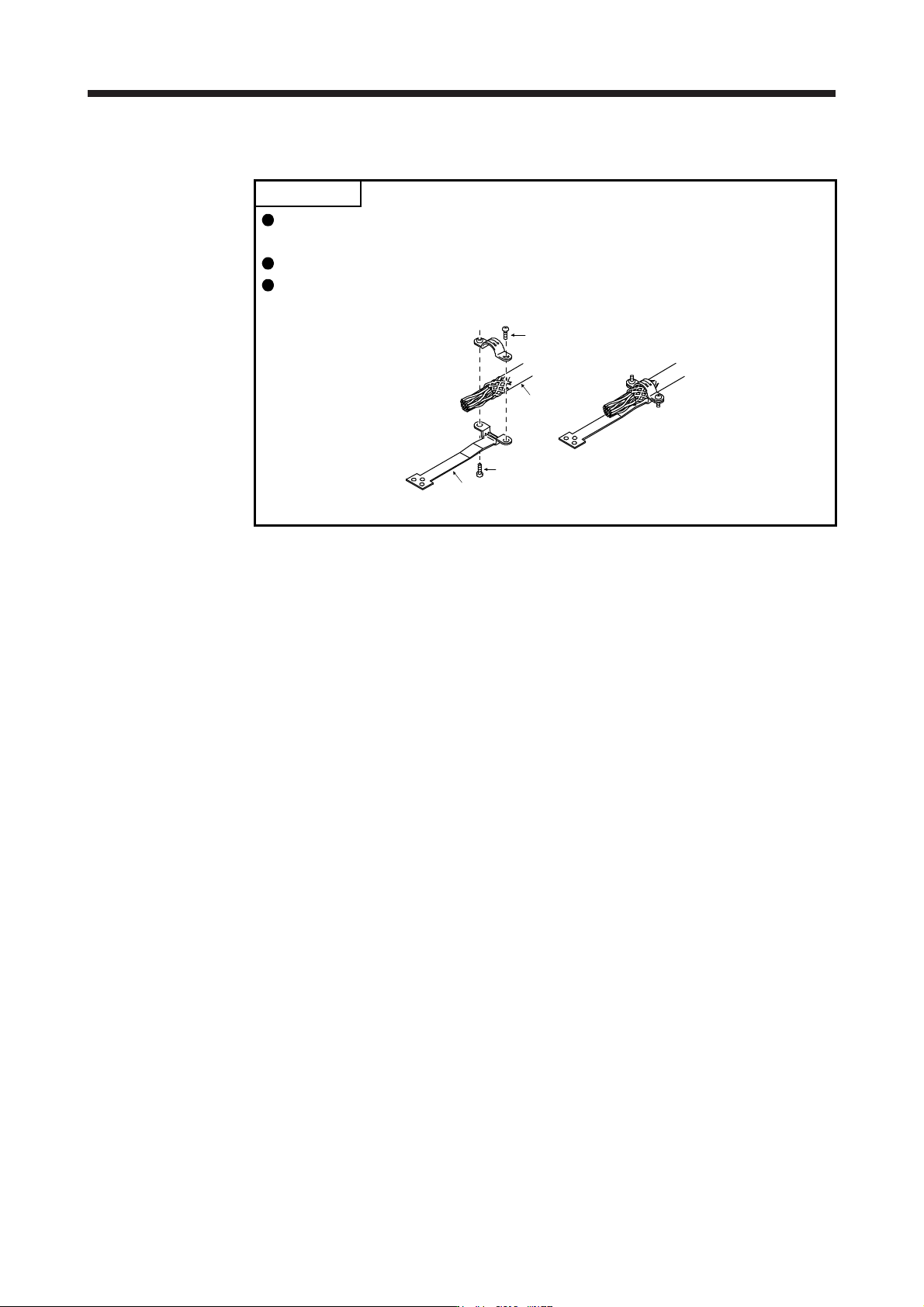
For the CN3 connector, securely connect the external conductor of the shielded
cable to the ground plate and fix it to the connector shell.
Screw
Screw
Ground plate
Cable