sh030106u.pdf - 第102页
3. SIG NALS A ND WIRI NG 3 - 25 The servo ampl ifier front vi ew show n is that of the MR -J4-20B o r less . Refer to ch apter 9 DIM ENSIONS for the appear ances a nd conn ector lay outs of t he other ser vo ampli f iers…
3. SIGNALS AND WIRING
3 - 24
3.4 Connectors and pin assignment
POINT
The pin assignment of the connectors is as viewed from the cable connector
wiring section.
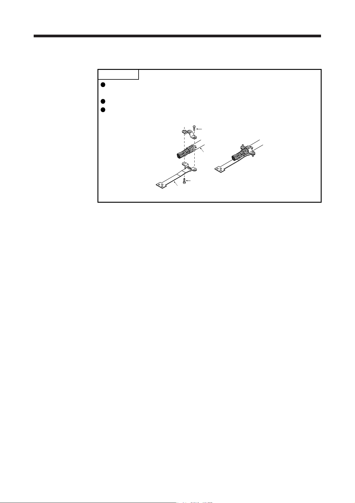
For the STO I/O signal connector (CN8), refer to chapter 13.
For the CN3 connector, securely connect the external conductor of the shielded
cable to the ground plate and fix it to the connector shell.
Screw
Screw
Ground plate
Cable
3. SIGNALS AND WIRING
3 - 25
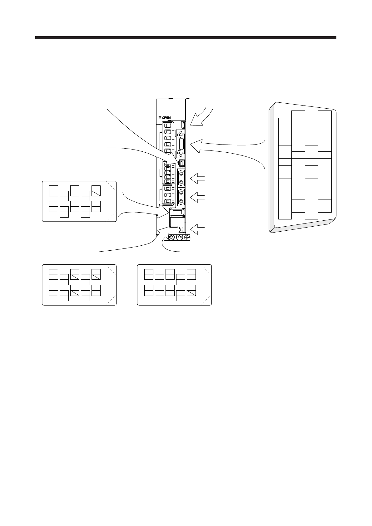
The servo amplifier front view shown is that of the MR-J4-20B or less. Refer to chapter 9 DIMENSIONS for
the appearances and connector layouts of the other servo amplifiers.
The frames of the CN2 and CN3 connectors are connected to the protective earth terminal in the servo
amplifier.
CN3
1
2
3
5
4
6
7
9
8
10
11
12
13
14
15
16
17
18
19
20
DI1
MO1
DICOM
LG
DOCOM
DICOM
LZ
DI2
MO2
EM2
LG
MBR
LBR
LA
LB
LZR
LAR
ALM
DI3INP
4
MRR
2
LG 8
6
1
P5
5
10
3
MR
7
9
BAT
MXR
MX
CN8
4
MRR2
2
LG 8
6
1
P5
5
10
3
MR2
7
9
MXR2
MX2
CN2L (Note 1, 2)
4
PAR
2
LG 8
6
1
P5
5
10
3
PA
7
9
PB
PZR
PZ
PBR PSEL
(for using serial encoder)
CN2L (Note 1, 2)
(for using A/B/Z-phase pulse encoder)
THM2
THM1
CN2 (Note 2)
CN5 (USB connector)
Refer to section 11.7
CN1A
Connector for SSCNET III
cable for previous servo
amplifier axis
CN1B
Connector for SSCNET III
cable for next servo
amplifier axis
CN4
(Battery connector)
Refer to section 11.8
For the STO I/O signal
connector, refer to section 13.2.
BAT
Note 1. The MR-J4-_B_ servo amplifiers have CN2L connectors. This CN2L is a connector of 3M.
When usin
g
an
y
other connector, refer to each servo motor instruction manual.
2. Refer to table 1.1 and "Linear Encoder Instruction Manual" for connections of external encoders.
3. SIGNALS AND WIRING
3 - 26
3.5 Signal (device) explanations
For the I/O interfaces (symbols in I/O division column in the table), refer to section 3.8.2.
The pin numbers in the connector pin No. column are those in the initial status.
3.5.1 Input device
Device Symbol
Connector
pin No.
Function and application
I/O
division
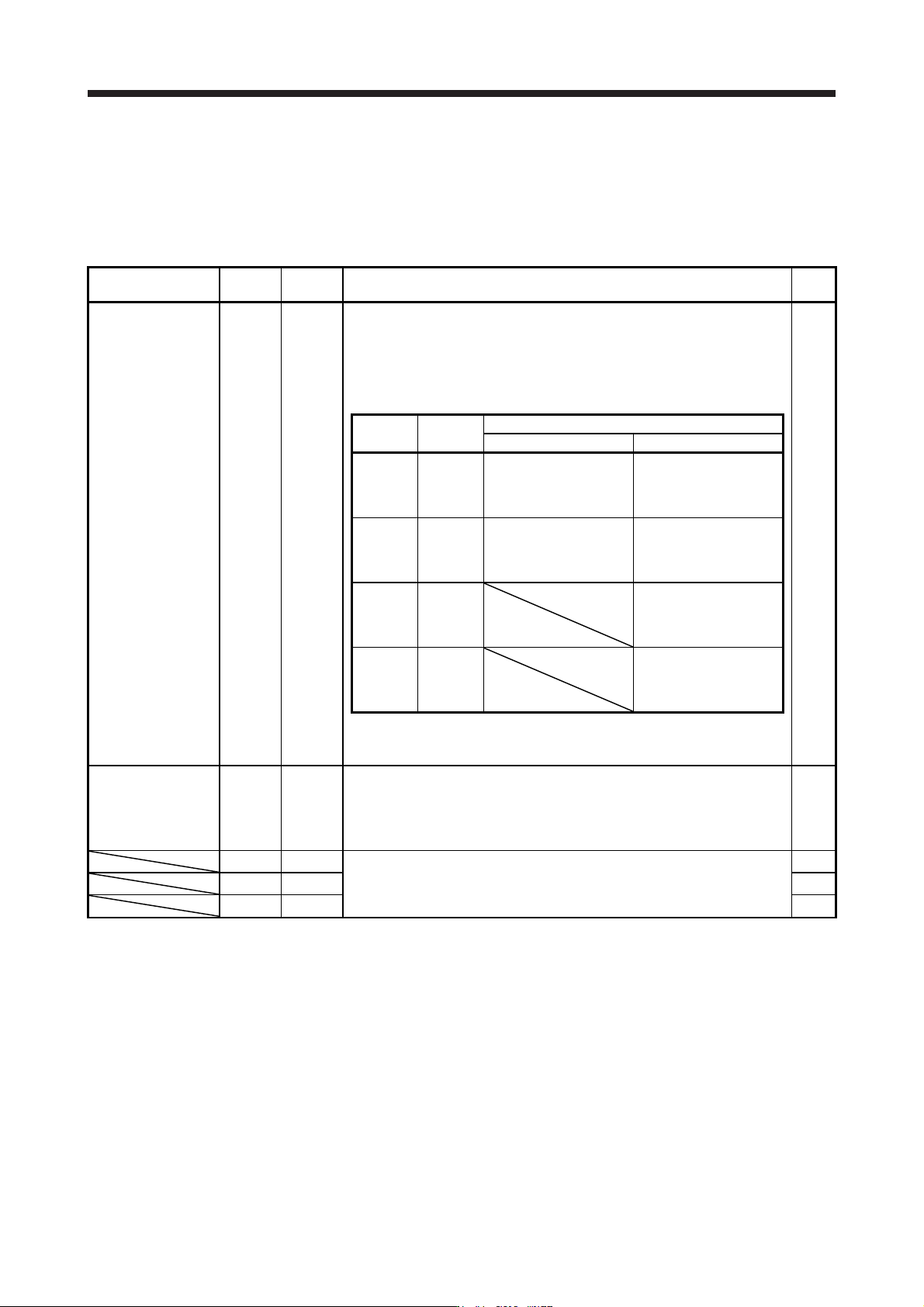
Forced stop 2 EM2 CN3-20
Turn off EM2 (open between commons) to decelerate the servo motor to a stop
with commands.
Turn EM2 on (short between commons) in the forced stop state to reset that
state.
Set [Pr. PA04] to "2 1 _ _" to disable EM2.
The following shows the setting of [Pr. PA04].
DI-1
[Pr. PA04]
setting
EM2/EM1
Deceleration method
EM2 or EM1 is off Alarm occurred
0 0 _ _ EM1
MBR (Electromagnetic
brake interlock) turns off
without the forced stop
deceleration.
MBR (Electromagnetic
brake interlock) turns off
without the forced stop
deceleration.
2 0 _ _ EM2
MBR (Electromagnetic
brake interlock) turns off
after the forced stop
deceleration.
MBR (Electromagnetic
brake interlock) turns off
after the forced stop
deceleration.
0 1 _ _
Not using
EM2 and
EM1
MBR (Electromagnetic
brake interlock) turns off
without the forced stop
deceleration.
2 1 _ _
Not using
EM2 and
EM1
MBR (Electromagnetic
brake interlock) turns off
after the forced stop
deceleration.
EM2 and EM1 are mutually exclusive.
EM2 has the same function as EM1 in the torque control mode.
Forced stop 1 EM1 (CN3-20) When using EM1, set [Pr. PA04] to "0 0 _ _" to enable EM1.
When EM1 is turned off (open between commons), the base circuit shuts off,
and the dynamic brake operates to decelerate the servo motor to a stop.
The forced stop will be reset when EM1 is turned on (short between commons).
Set [Pr. PA04] to "0 1 _ _" to disable EM1.
DI-1
DI1 CN3-2
Devices can be assigned for these signals with controller setting. For devices
that can be assigned, refer to the controller instruction manual. The following
devices can be assigned for MR-J4 compatible controller (R_MTCPU,
Q17_DSCPU, RD77MS_ and QD77MS_).
DI-1
DI2 CN3-12 DI-1
DI3 CN3-19 DI-1