sh030106u.pdf - 第106页
3. SIG NALS A ND WIRI NG 3 - 29 3.6 Forced stop dec elerati on funct ion POINT When alar ms not r elated to the forc ed stop func tion oc c ur, cont rol of motor decelerati on cannot be gua ranteed. ( Refer to c hapter 8…

3. SIGNALS AND WIRING
3 - 28
Device Symbol Function and application
Limiting torque TLC
When the torque reaches the torque limit value during torque generation, TLC will turn on. When
the servo is off, TLC will be turned off.
This device cannot be used in the torque control mode.
Warning WNG
When warning has occurred, WNG turns on. When a warning is not occurring, WNG will turn off in
2.5 s to 3.5 s after power-on.
Battery warning BWNG
BWNG turns on when [AL. 92 Battery cable disconnection warning] or [AL. 9F Battery warning] has
occurred. When the battery warning is not occurring, BWNG will turn off in 2.5 s to 3.5 s after
power-on.
Variable gain
selection
CDPS CDPS will turn on during variable gain.
Absolute position
undetermined
ABSV ABSV turns on when the absolute position is undetermined.
The device cannot be used in the speed control mode and torque control mode.
During tough drive MTTR
When a tough drive is enabled in [Pr. PA20], activating the instantaneous power failure tough drive
will turn on MTTR.
During fully closed
loop control
CLDS CLDS turns on during fully closed loop control.
3.5.3 Output signal
Signal name Symbol
Connector
pin No.
Function and application
Encoder A-phase
pulse (differential line
driver)
LA
LAR
CN3-6
CN3-16
These devices output pulses of encoder output set in [Pr. PA15] and [Pr. PA16] in the
differential line driver type.
In CCW rotation of the servo motor, the encoder B-phase pulse lags the encoder A-
phase pulse by a phase angle of π/2.
The relation between rotation direction and phase difference of the A-phase and B-
phase pulses can be changed with [Pr. PC03].
Output pulse specification, dividing ratio setting, and electronic gear setting can be
selected.
Depending on the servo motor stop position, the encoder output pulse may turn on and
off repeatedly even if the servo motor is stopped.
Encoder B-phase
pulse (differential line
driver)
LB
LBR
CN3-7
CN3-17
Encoder Z-phase
pulse (differential line
driver)
LZ
LZR
CN3-8
CN3-18
The encoder zero-point signal is output in the differential line driver type. One pulse is
output per servo motor revolution. This turns on when the zero-point position is
reached. (negative logic)
The minimum pulse width is about 400 μs. For home position return using this pulse,
set the creep speed to 100 r/min or less.
Analog monitor 1 MO1 CN3-4
This is used to output the data set in [Pr. PC09] to between MO1 and LG in terms of
voltage.
Resolution: 10 bits or equivalent
Analog monitor 2 MO2 CN3-14
This signal output the data set in [Pr. PC10] to between MO2 and LG in terms of
voltage.
Resolution: 10 bits or equivalent
3.5.4 Power supply
Signal name Symbol
Connector
pin No.
Function and application
Digital I/F power
supply input
DICOM CN3-5
CN3-10
Input 24 V DC (24 V DC ± 10% 300 mA) for I/O interface. The power supply capacity
changes depending on the number of I/O interface points to be used.
For sink interface, connect + of 24 V DC external power supply.
For source interface, connect - of 24 V DC external power supply.
Digital I/F common DOCOM CN3-3
Common terminal of input signal such as EM2 of the servo amplifier. This is separated
from LG.
For sink interface, connect - of 24 V DC external power supply.
For source interface, connect + of 24 V DC external power supply.
Monitor common LG CN3-1
CN3-11
Common terminal of MO1 and MO2.
Pins are connected internally.
Shield SD Plate Connect the external conductor of the shielded wire.
3. SIGNALS AND WIRING
3 - 29
3.6 Forced stop deceleration function
POINT
When alarms not related to the forced stop function occur, control of motor
deceleration cannot be guaranteed. (Refer to chapter 8.)
When SSCNET III/H communication shut-off occurs, forced stop deceleration
will operate. (Refer to section 3.7.1 (3).)
In the torque control mode, the forced stop deceleration function is not available.
Disable the forced stop deceleration function for a machine in which multiple
axes are connected together, such as a tandem structure. If an alarm occurs
with the forced stop deceleration function disabled, the servo motor will stop with
the dynamic brake.
Keep the servo-on command (from controller) and ready-on command (from
controller) on while EM2 (Forced stop 2) is off. When the servo-on command
(from controller) or ready-on command (from controller) is off, forced stop
deceleration, base circuit shut-off delay time, and vertical axis freefall prevention
do not function.
3.6.1 Forced stop deceleration function
When EM2 is turned off, dynamic brake will start to stop the servo motor after forced stop deceleration.
During this sequence, the display shows [AL. E6 Servo forced stop warning].
During normal operation, do not use EM2 (Forced stop 2) to alternate stop and drive. The servo amplifier life
may be shortened.
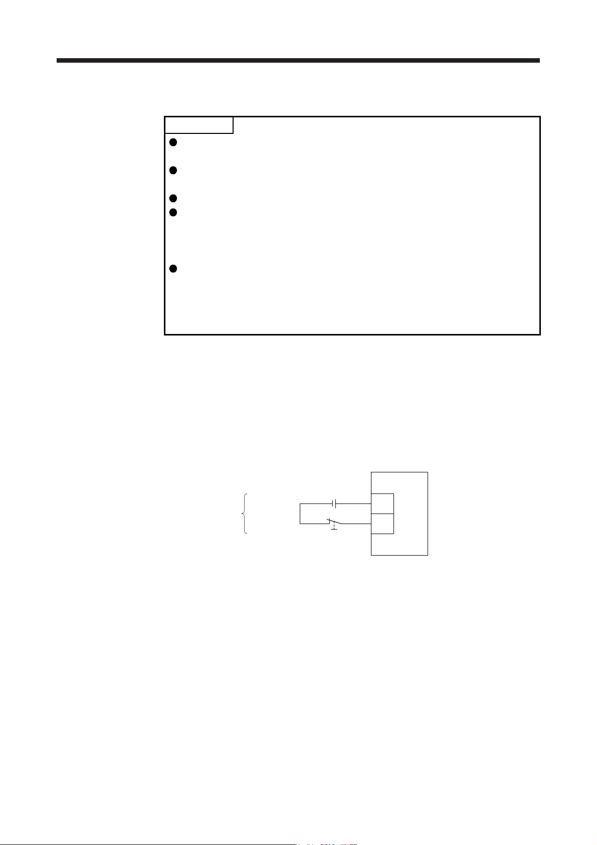
(1) Connection diagram
Servo amplifie
r
Forced stop 2
DICOM
EM2
24 V DC
(Note)
Note. This diagram shows sink I/O interface. For source I/O interface, refer to section
3.8.3.
3. SIGNALS AND WIRING
3 - 30
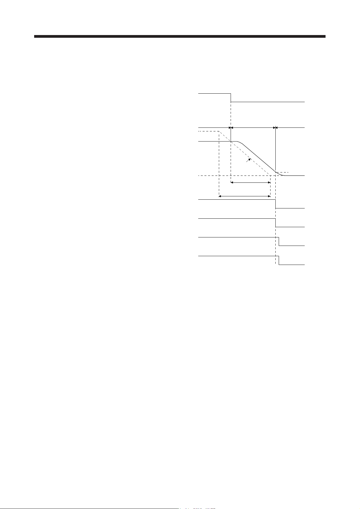
(2) Timing chart
When EM2 (Forced stop 2) is turned off, the motor will decelerate according to [Pr. PC24 Forced stop
deceleration time constant]. Once the motor speed is below [Pr. PC07 Zero speed], base power is cut
and the dynamic brake activates.
0 r/min
ON
OFF (Enabled)
ON
OFF
Servo-on command
(from controller)
Ready-on command
(from controller)
ON
OFF
ON
OFF
ON
[Pr. PC24]
Deceleration time
Command
Ordinary
operation
Forced stop
deceleration
Dynamic brake
+
Electromagnetic brake
Zero speed
([Pr. PC07])
Base circuit
(Energy supply to
the servo motor)
Servo motor speed
MBR
(Electromagnetic
brake interlock)
Rated Speed
EM2 (Forced stop 2)
OFF (Enabled)