sh030106u.pdf - 第107页
3. SIG NALS A ND WIRI NG 3 - 30 (2) Timing ch art When EM2 (Forced stop 2) is turned of f, the motor w ill decel era te acc ording to [Pr. PC24 Forc ed stop decelerati on tim e consta nt]. Onc e the mot or spee d is b el…
3. SIGNALS AND WIRING
3 - 29
3.6 Forced stop deceleration function
POINT
When alarms not related to the forced stop function occur, control of motor
deceleration cannot be guaranteed. (Refer to chapter 8.)
When SSCNET III/H communication shut-off occurs, forced stop deceleration
will operate. (Refer to section 3.7.1 (3).)
In the torque control mode, the forced stop deceleration function is not available.
Disable the forced stop deceleration function for a machine in which multiple
axes are connected together, such as a tandem structure. If an alarm occurs
with the forced stop deceleration function disabled, the servo motor will stop with
the dynamic brake.
Keep the servo-on command (from controller) and ready-on command (from
controller) on while EM2 (Forced stop 2) is off. When the servo-on command
(from controller) or ready-on command (from controller) is off, forced stop
deceleration, base circuit shut-off delay time, and vertical axis freefall prevention
do not function.
3.6.1 Forced stop deceleration function
When EM2 is turned off, dynamic brake will start to stop the servo motor after forced stop deceleration.
During this sequence, the display shows [AL. E6 Servo forced stop warning].
During normal operation, do not use EM2 (Forced stop 2) to alternate stop and drive. The servo amplifier life
may be shortened.
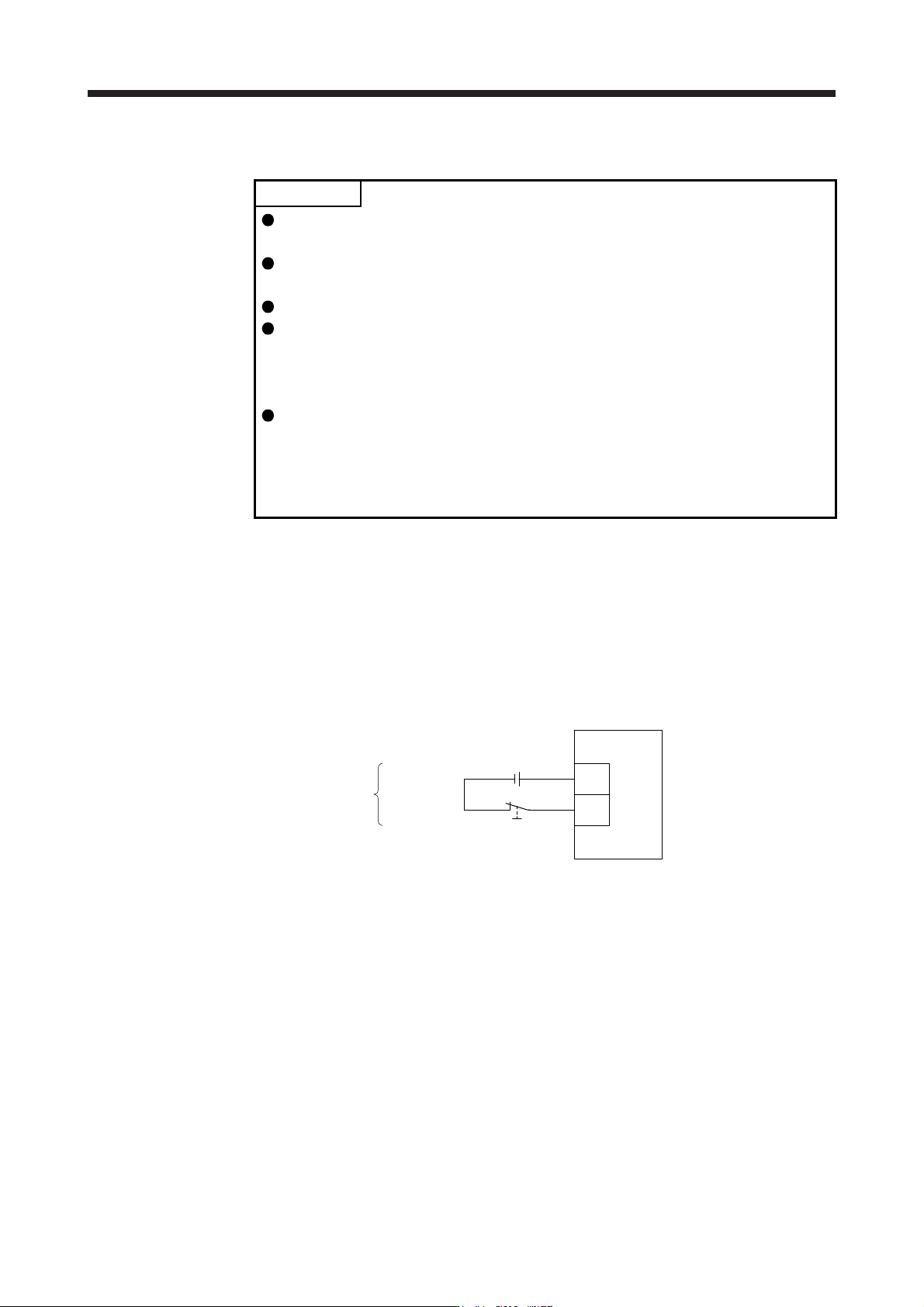
(1) Connection diagram
Servo amplifie
r
Forced stop 2
DICOM
EM2
24 V DC
(Note)
Note. This diagram shows sink I/O interface. For source I/O interface, refer to section
3.8.3.
3. SIGNALS AND WIRING
3 - 30
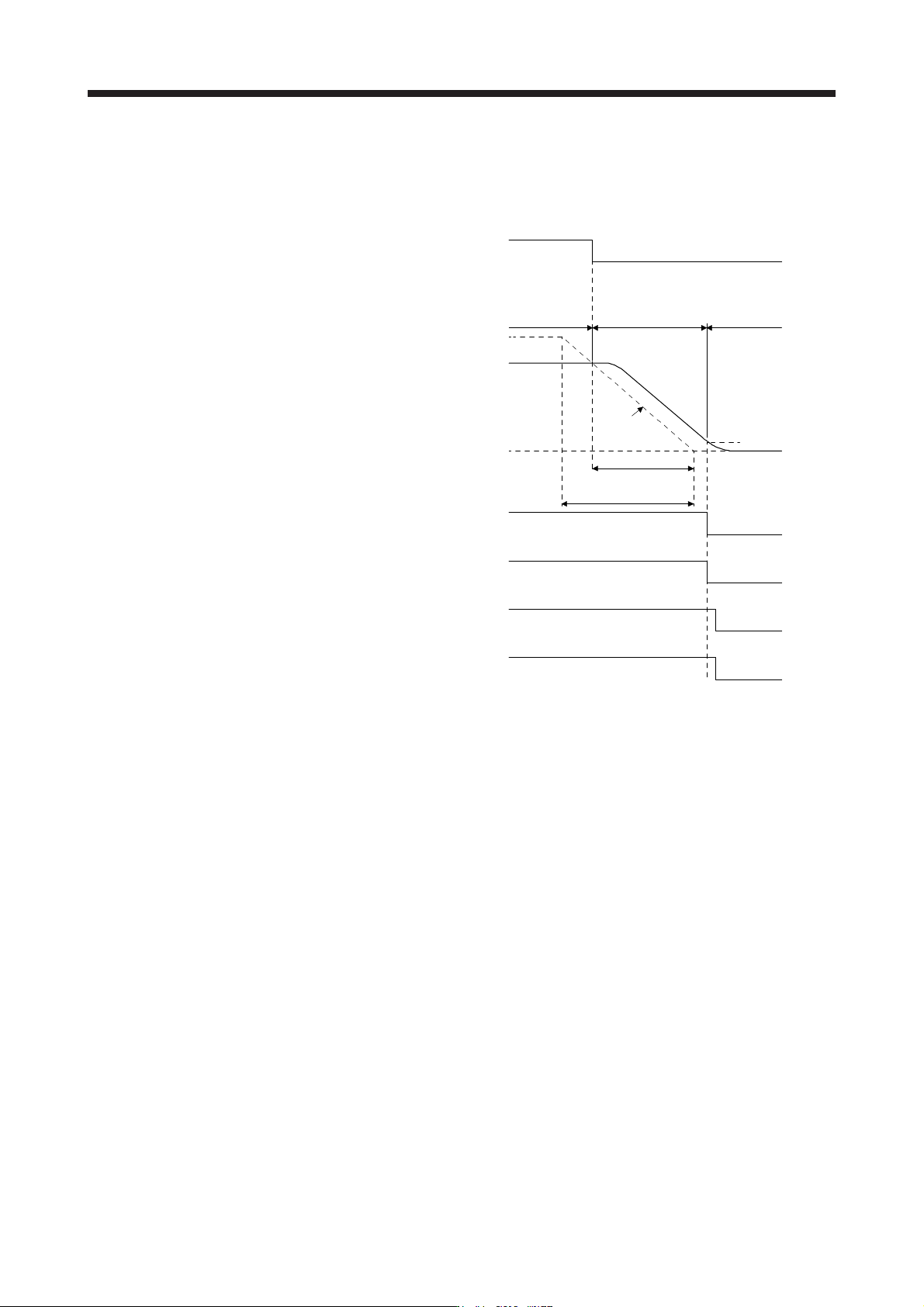
(2) Timing chart
When EM2 (Forced stop 2) is turned off, the motor will decelerate according to [Pr. PC24 Forced stop
deceleration time constant]. Once the motor speed is below [Pr. PC07 Zero speed], base power is cut
and the dynamic brake activates.
0 r/min
ON
OFF (Enabled)
ON
OFF
Servo-on command
(from controller)
Ready-on command
(from controller)
ON
OFF
ON
OFF
ON
[Pr. PC24]
Deceleration time
Command
Ordinary
operation
Forced stop
deceleration
Dynamic brake
+
Electromagnetic brake
Zero speed
([Pr. PC07])
Base circuit
(Energy supply to
the servo motor)
Servo motor speed
MBR
(Electromagnetic
brake interlock)
Rated Speed
EM2 (Forced stop 2)
OFF (Enabled)
3. SIGNALS AND WIRING
3 - 31
3.6.2 Base circuit shut-off delay time function
The base circuit shut-off delay time function is used to prevent vertical axis from dropping at a forced stop
(EM2 goes off), alarm occurrence, or SSCNET III/H communication shut-off due to delay time of the
electromagnetic brake. Set the time from MBR (Electromagnetic brake interlock) off to base circuit shut-off
with [Pr. PC02].
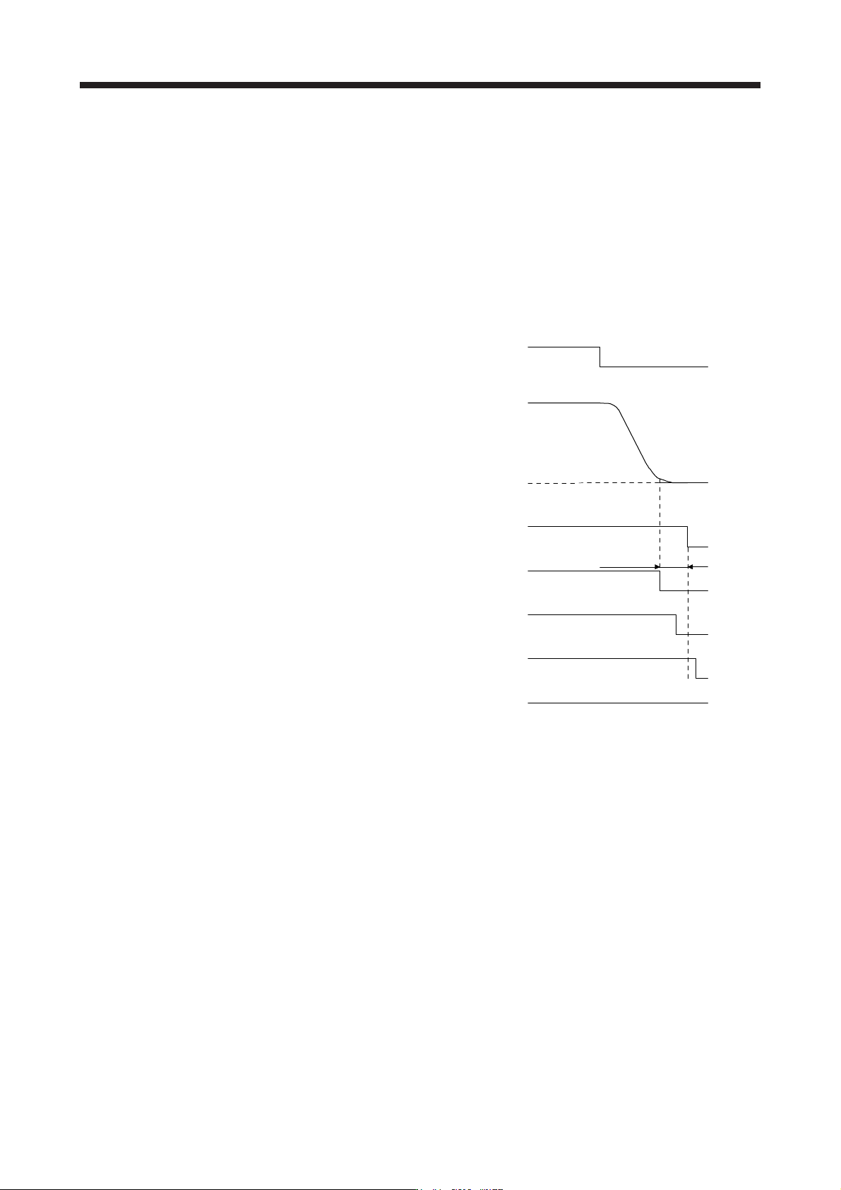
(1) Timing chart
When EM2 (Forced stop 2) turns off or an alarm occurs during driving, the servo motor will decelerate
based on the deceleration time constant. MBR (Electromagnetic brake interlock) will turn off, and then
after the delay time set in [Pr. PC02], the servo amplifier will be base circuit shut-off status.
ON
0 r/min
ON
ON
OFF
Servo-on command
(from controller)
Ready-on command
(from controller)
ON
OFF
Electromagnetic brake
ON
OFF
Release
Activate
[Pr. PC02]
MBR
(Electromagnetic
brake interlock)
Base circuit
(Energy supply to
t
he servo motor)
Servo motor speed
OFF (Enabled)
OFF (Enabled)
EM2 (Forced stop 2)
(2) Adjustment
While the servo motor is stopped, turn off EM2 (Forced stop 2), adjust the base circuit shut-off delay time
in [Pr. PC02], and set the value to approximately 1.5 times of the smallest delay time in which the servo
motor shaft does not freefall.