sh030106u.pdf - 第111页
3. SIG NALS A ND WIRI NG 3 - 34 (2) When the for ced s top dec eleratio n functio n is not enabl ed MBR (Electromagnetic brake interlock) ON OFF ON (no alarm) OFF (alarm) Base circuit (Energy supply to the servo motor) O…
3. SIGNALS AND WIRING
3 - 33
(3) If STO is turned off during forced stop deceleration, [AL. 63 STO timing error] will occur.
3.7 Alarm occurrence timing chart
CAUTION
When an alarm has occurred, remove its cause, make sure that the operation
signal is not being input, ensure safety, and reset the alarm before restarting
operation.
POINT
In the torque control mode, the forced stop deceleration function is not available.
To deactivate the alarm, cycle the control circuit power or give the error reset or CPU reset command from
the servo system controller. However, the alarm cannot be deactivated unless its cause is removed.
3.7.1 When you use the forced stop deceleration function
POINT
To enable the function, set "2 _ _ _ (initial value)" in [Pr. PA04].
Disable the forced stop deceleration function for a machine in which multiple
axes are connected together, such as a tandem structure. If an alarm occurs
with the forced stop deceleration function disabled, the servo motor will stop with
the dynamic brake.
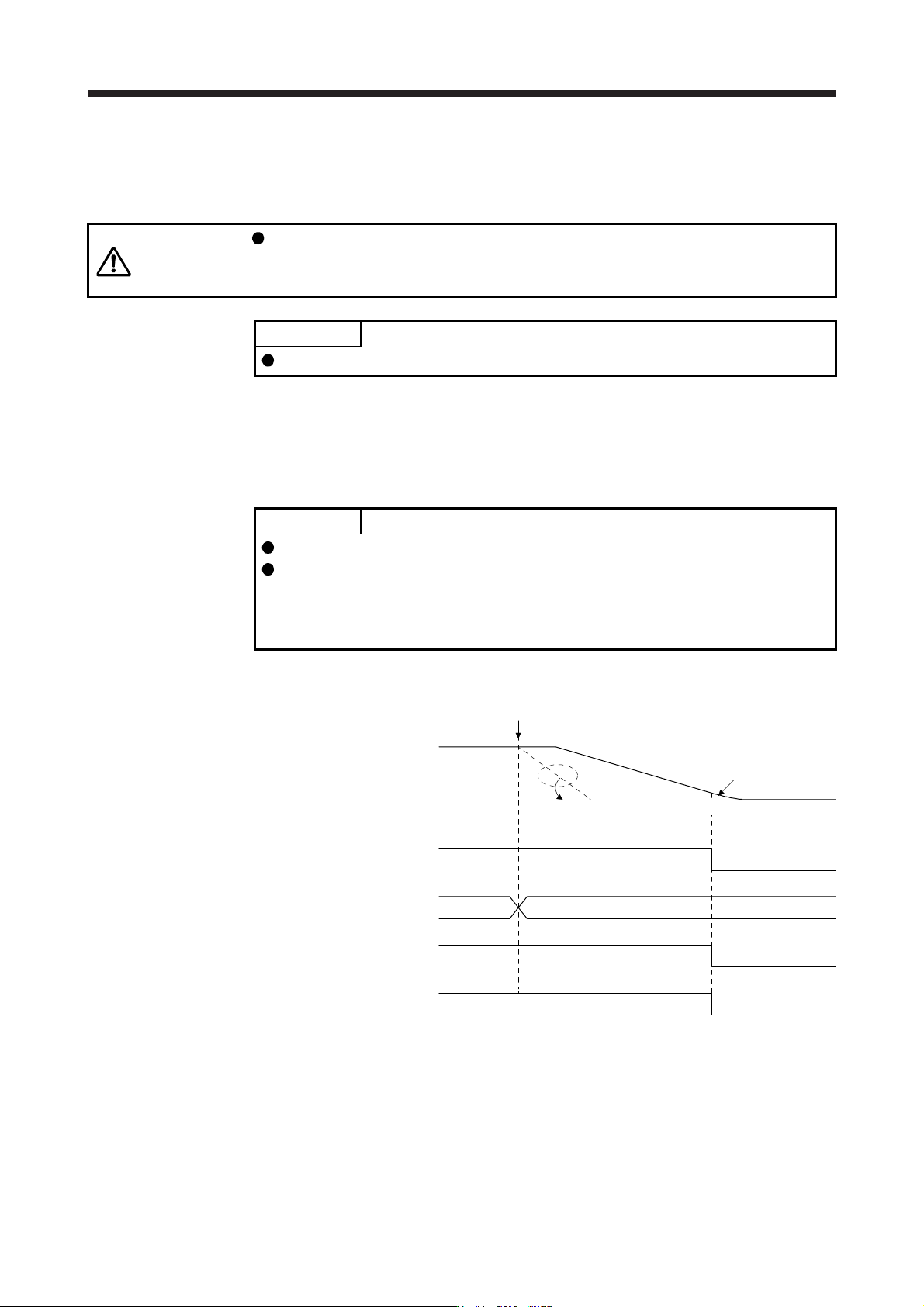
(1) When the forced stop deceleration function is enabled
Alarm occurrence
Alarm No.No alarm
(Note)
Model speed command 0
and equal to or less than
zero speed
MBR
(Electromagnetic
brake interlock)
ON
OFF
ON (no alarm)
OFF (alarm)
Base circuit
(Energy supply to
the servo motor)
ON
OFF
Servo amplifier
display
0 r/min
Servo motor speed
ALM (Malfunction)
Controller command is not received.
Note. The model speed command is a speed command generated in the servo amplifier for forced stop deceleration
of the servo motor.
3. SIGNALS AND WIRING
3 - 34
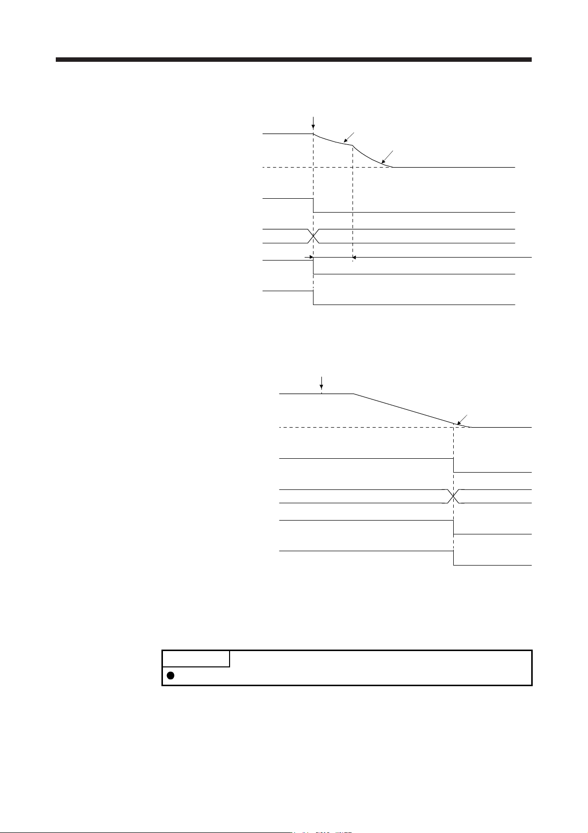
(2) When the forced stop deceleration function is not enabled
MBR
(Electromagnetic
brake interlock)
ON
OFF
ON (no alarm)
OFF (alarm)
Base circuit
(Energy supply to
the servo motor)
ON
OFF
Servo amplifier
display
0 r/min
Servo motor speed
ALM (Malfunction)
No alarm Alarm No.
Braking by the dynamic brake
Dynamic brake
+ Braking by the electromagnetic brake
Operation delay time of the electromagnetic brake
Alarm occurrence
(3) When SSCNET III/H communication shut-off occurs
The dynamic brake may operate depending on the communication shut-off status.
MBR
(Electromagnetic
brake interlock)
ON
OFF
ON (no alarm)
OFF (alarm)
Base circuit
(Energy supply to
the servo motor)
ON
OFF
Servo amplifier
display
0 r/min
Servo motor speed
A
LM (Malfunction)
AANo alarm (d1 or E7)
SSCNET III/H communication
has broken.
(Note)
Model speed command 0
and equal to or less than
zero speed
Note. The model speed command is a speed command generated in the servo amplifier for forced stop deceleration
of the servo motor.
3.7.2 When you do not use the forced stop deceleration function
POINT
To disable the function, set "0 _ _ _" in [Pr. PA04].
The timing chart that shows the servo motor condition when an alarm or SSCNET III/H communication shut-
off occurs is the same as section 3.7.1 (2).
3. SIGNALS AND WIRING
3 - 35
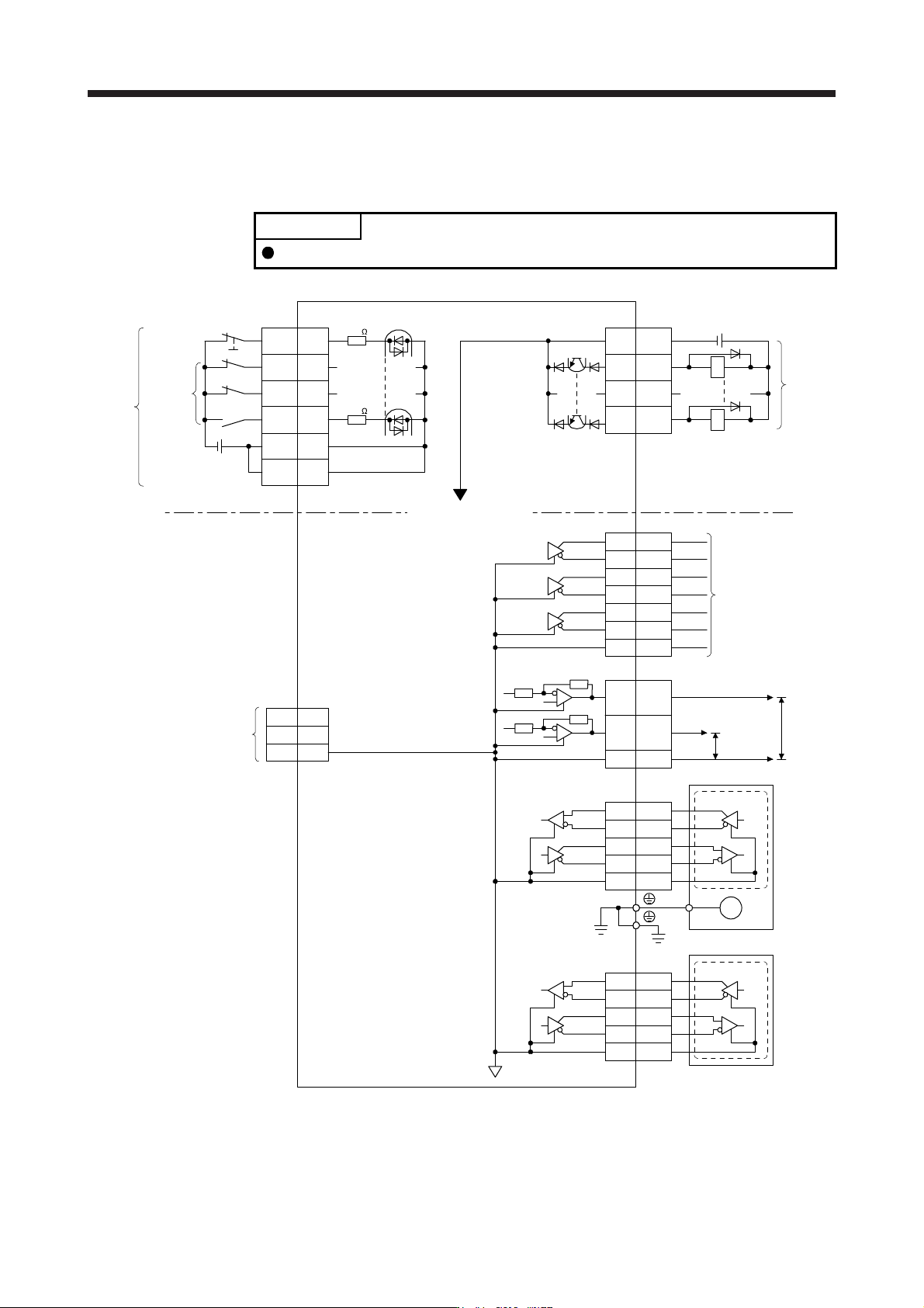
3.8 Interfaces
3.8.1 Internal connection diagram
POINT
Refer to section 13.3.1 for the CN8 connector.
3
CN3
6
16
7
17
8
18
LA
LAR
LB
LBR
LZ
LZR
2
4
7
8
MR
MRR
MX
MXR
LG
PE
M
CN2
CN3
MO1
MO2
LG
4
14
1
LG11
EM2
CN3
20
DI1 2
DI2 12
DI3 19
DICOM
5
10
CN3
3
13
9
15
DOCOM
INP
ALM
USB
D+
GND
D- 2
3
5
CN5
MBR
DICOM
RA
RA
3
2
4
7
8
MR2
MRR2
MX2
MXR2
LG
External encoder
(Note 4, 6) CN2L
±10 V DC
±10 V DC
Encoder
Differential line
driver output
(35 mA or less)
Servo motor
Analog monitor
(Note 2)
Servo amplifier
(Note 1)
24 V DC
Forced stop 2
(Note 3)
(Note 3)
Isolated
Approximately
6.2 k
Approximately
6.2 k
Encoder
(Note 5)
24 V DC
(Note 5)
Note 1. Signal can be assigned for these pins with the controller setting.
For contents of signals, refer to the instruction manual of the controller.
2. The signal cannot be used in the speed control mode and torque control mode.
3. This diagram shows sink I/O interface. For source I/O interface, refer to section 3.8.3.
4. This is for MR-J4-_B_-RJ servo amplifier. MR-J4-_B_ servo amplifier does not have CN2L connector.
5. The illustration of the 24 V DC power supply is divided between input signal and output signal for convenience. However, they
can be configured by one.
6. Refer to table 1.1 for connections of external encoders.