sh030106u.pdf - 第115页
3. SIG NALS A ND WIRI NG 3 - 38 3.8.3 Sourc e I/O interf aces In this serv o amplifi er, sourc e type I/O interfaces c an be used . (1) Digital i nput in terface D I-1 This is a n input circ uit whos e photoc oupler anod…
3. SIGNALS AND WIRING
3 - 37
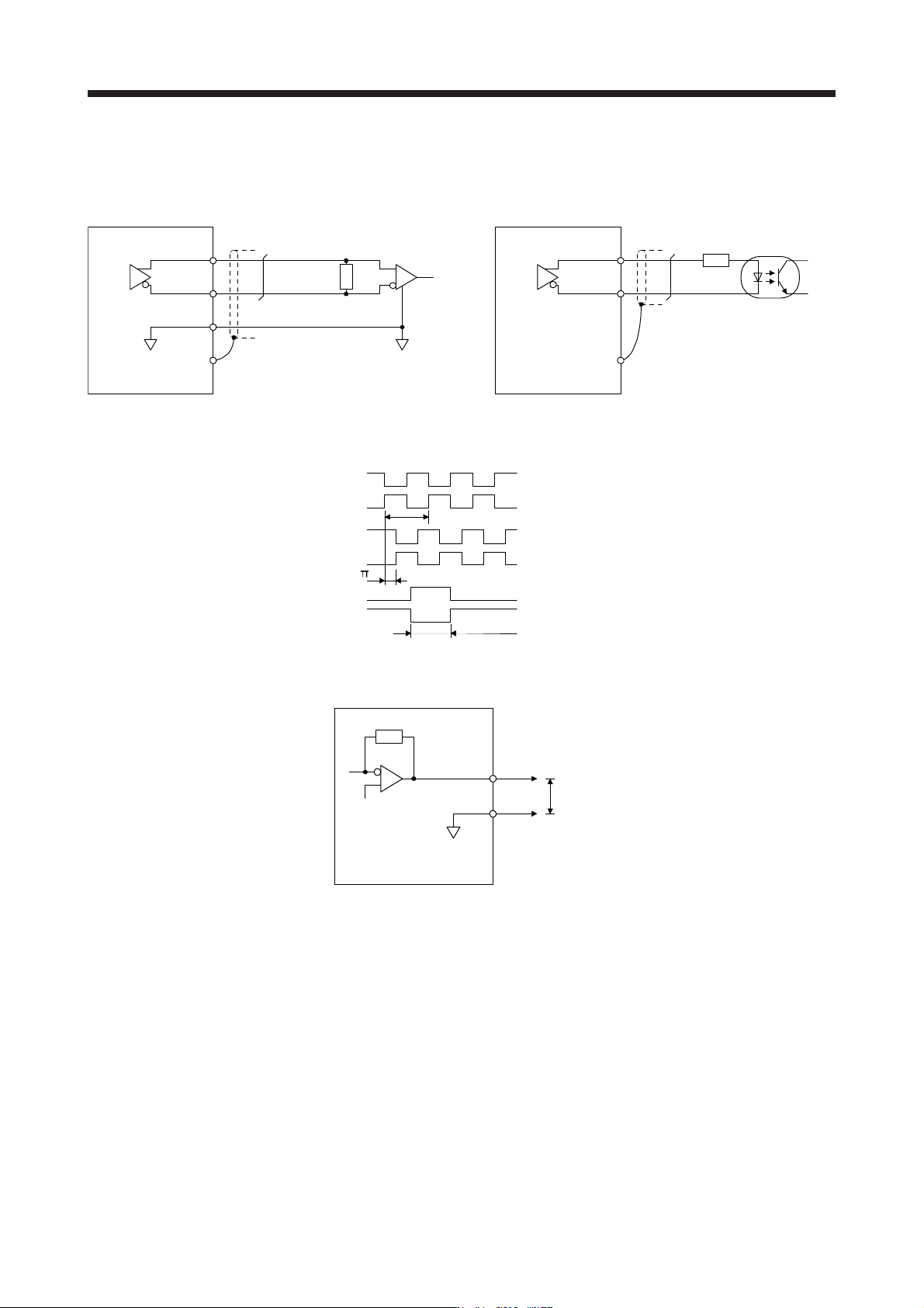
(3) Encoder output pulses DO-2 (differential line driver type)
(a) Interface
Maximum output current: 35 mA
150 Ω
100 ΩAm26LS32 or equivalent
Servo amplifier
LA
(LB, LZ)
LAR
(LBR, LZR)
SD
LG
High-speed photocoupler
Servo amplifier
LAR
(LBR, LZR)
SD
LA
(LB, LZ)
(b) Output pulse
/2
LAR
T
Servo motor CCW rotation
Time cycle (T) is determined by the settings of
[Pr. PA15] and [Pr. PC03].
LA
LB
LBR
LZ
LZR
400 µs or more
(4) Analog output
LG
MO1
(MO2)
Servo amplifier
Output voltage: ±10 V
Maximum output current: 1 mA
Resolution: 10 bits or equivalent
Note. Output volta
g
e ran
g
e varies dependin
g
on the output contents.
3. SIGNALS AND WIRING
3 - 38
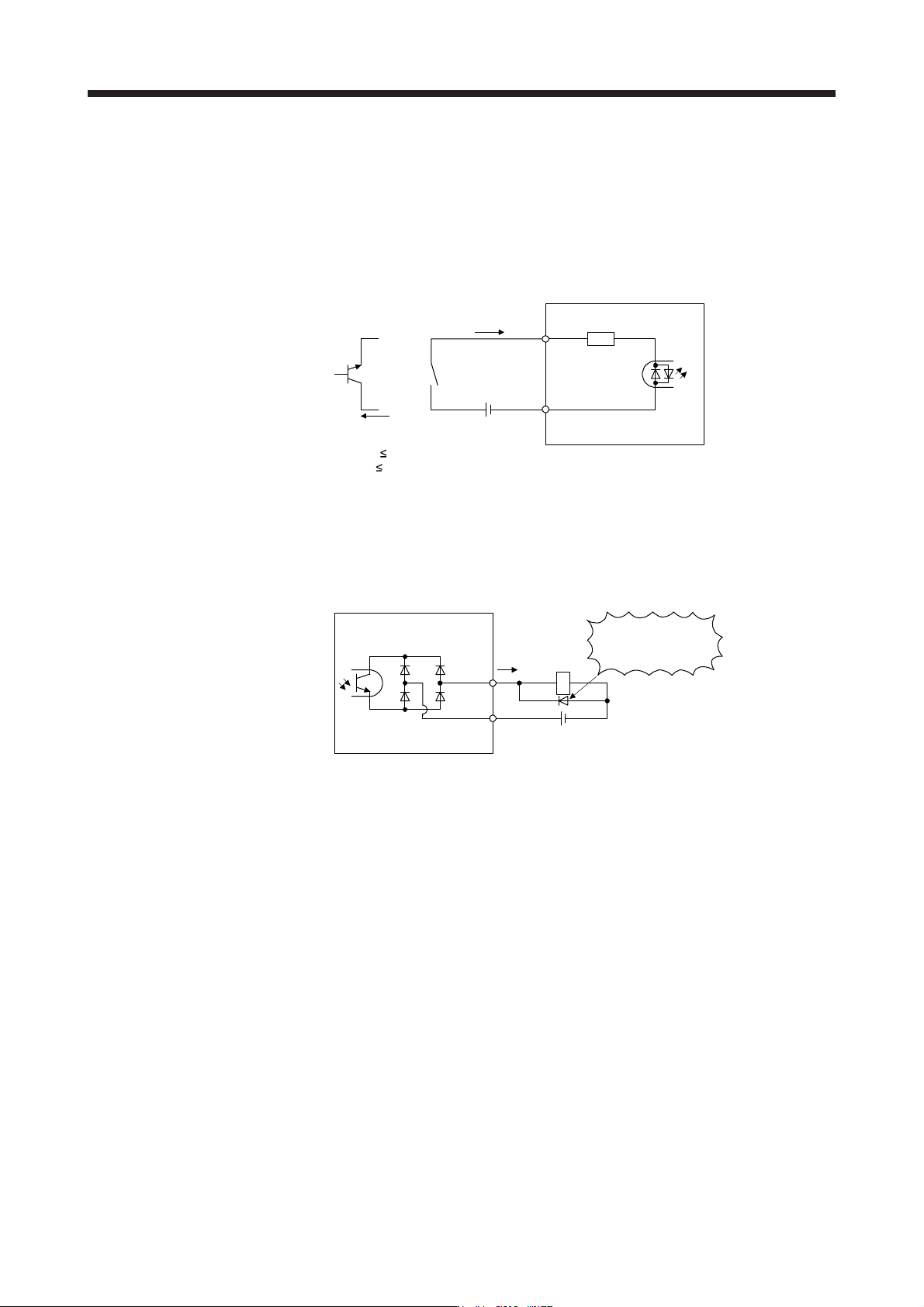
3.8.3 Source I/O interfaces
In this servo amplifier, source type I/O interfaces can be used.
(1) Digital input interface DI-1
This is an input circuit whose photocoupler anode side is the input terminal. Transmit signals from source
(open-collector) type transistor output, relay switch, etc.
V
CES
1.0 V
I
CEO
100 µA
Approximately
6.2 kΩ
DICOM
For transistor
Approximately
5 mA
TR
24 V DC ± 10%
300 mA
Switch
EM2,
etc.
Servo amplifier
(2) Digital output interface DO-1
This is a circuit in which the emitter of the output transistor is the output terminal. When the output
transistor is turned on, current will be applied from the output to a load.
A maximum of 2.6 V voltage drop occurs in the servo amplifier.
(Note) 24 V DC ± 10%
300 mA
If polarity of diode is
reversed, servo amplifier
will malfunction.
Servo amplifier
ALM,
etc.
Load
DOCOM
Note. If the voltage drop (maximum of 2.6 V) interferes with the relay operation, apply high
volta
g
e
(
maximum of 26.4 V
)
from external source.
3. SIGNALS AND WIRING
3 - 39
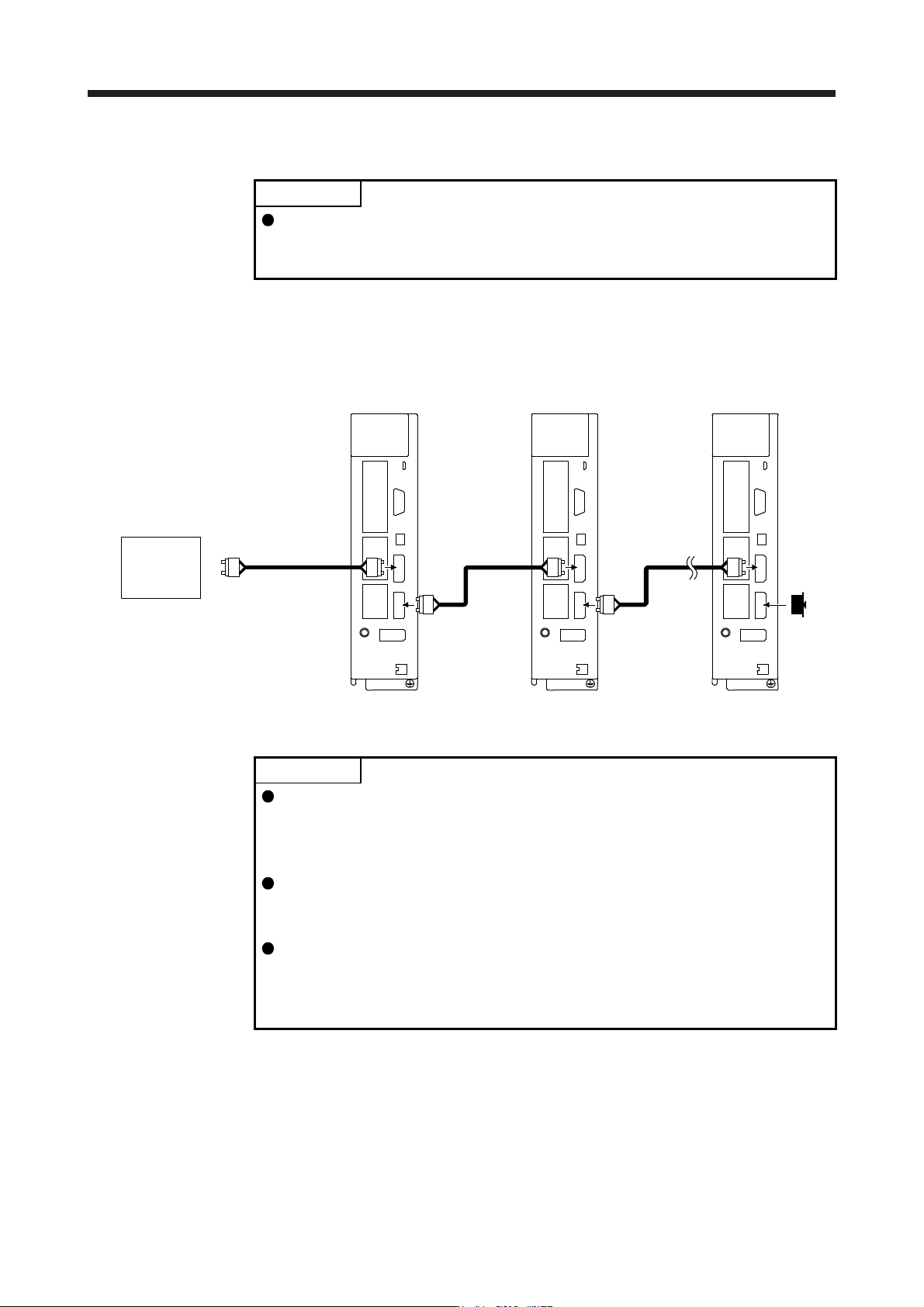
3.9 SSCNET III cable connection
POINT
Do not look directly at the light generated from CN1A/CN1B connector of the
servo amplifier or the end of SSCNET III cable. The light can be a discomfort
when it enters the eye.
(1) SSCNET III cable connection
For the CN1A connector, connect the SSCNET III cable connected to a controller in host side or a servo
amplifier of the previous axis. For CN1B connector, connect SSCNET III cable connected to servo
amplifier of the next axis. For CN1B connector of the final axis, put a cap came with servo amplifier.
The last axis servo amplifie
r
CN1B
CN1A
Cap
The second axis servo amplifie
r
CN1B
CN1A
SSCNET III
cable
SSCNET III cable
Controller
The first axis servo amplifie
r
CN1B
CN1A
SSCNET III
cable
(2) How to connect/disconnect cable
POINT
CN1A and CN1B connector are capped to protect light device inside connector
from dust. For this reason, do not remove the cap until just before connecting
the SSCNET III cable. Then, when removing SSCNET III cable, make sure to
put a cap.
Keep the cap for CN1A/CN1B connector and the tube for protecting optical cord
end of SSCNET III cable in a plastic bag with a slide fastener of SSCNET III
cable to prevent them from becoming dirty.
When asking repair of servo amplifier for some malfunctions, make sure to cap
CN1A and CN1B connector. When the connector is not put a cap, the light
device may be damaged at the transit. In this case, replacing and repairing the
light device is required.
(a) Connection
1) For SSCNET III cable in the shipping status, the tube for protect optical cord end is put on the
end of connector. Remove this tube.
2) Remove the CN1A and CN1B connector caps of the servo amplifier.