sh030106u.pdf - 第117页
3. SIG NALS A ND WIRI NG 3 - 40 3) With hold ing a t ab of S SCNE T III cable c onnector, m ake sure to insert it into th e CN1A and CN1 B connector o f the s ervo am plif ier unti l you hear the c lick . If t he end f a…
3. SIGNALS AND WIRING
3 - 39
3.9 SSCNET III cable connection
POINT
Do not look directly at the light generated from CN1A/CN1B connector of the
servo amplifier or the end of SSCNET III cable. The light can be a discomfort
when it enters the eye.
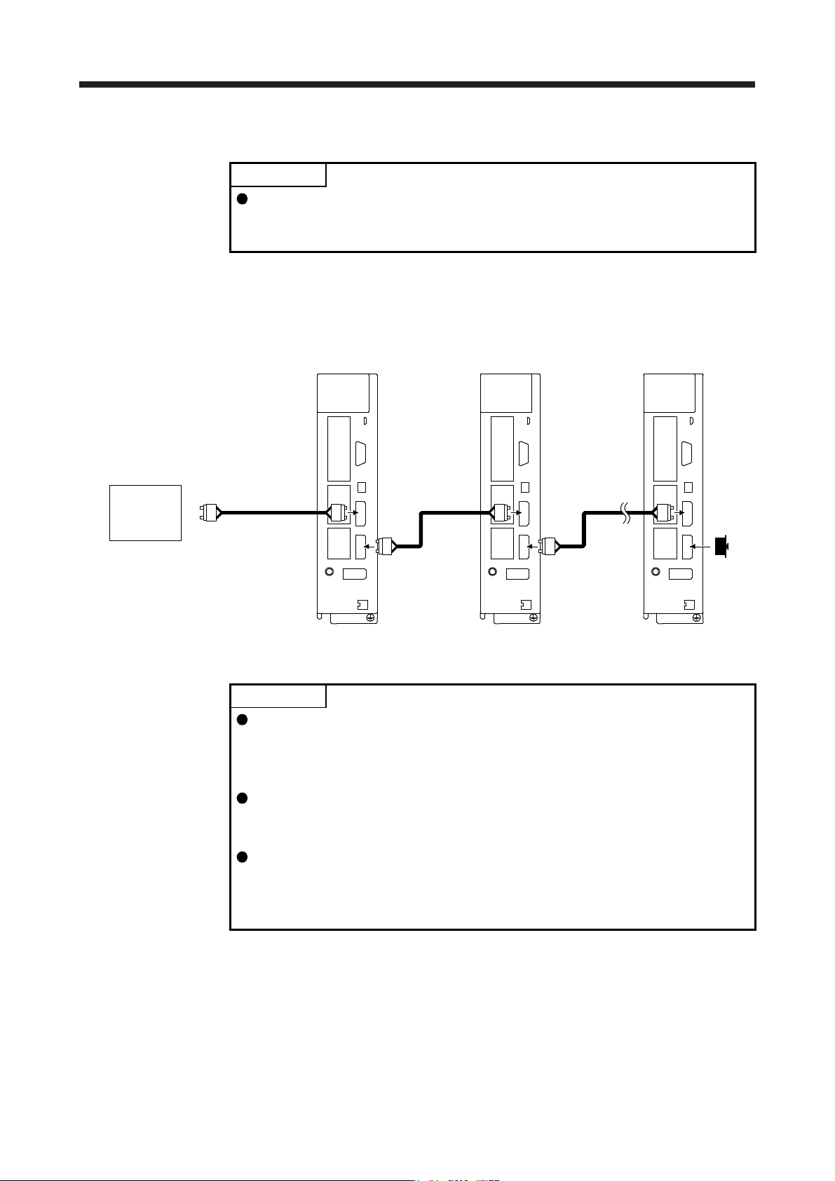
(1) SSCNET III cable connection
For the CN1A connector, connect the SSCNET III cable connected to a controller in host side or a servo
amplifier of the previous axis. For CN1B connector, connect SSCNET III cable connected to servo
amplifier of the next axis. For CN1B connector of the final axis, put a cap came with servo amplifier.
The last axis servo amplifie
r
CN1B
CN1A
Cap
The second axis servo amplifie
r
CN1B
CN1A
SSCNET III
cable
SSCNET III cable
Controller
The first axis servo amplifie
r
CN1B
CN1A
SSCNET III
cable
(2) How to connect/disconnect cable
POINT
CN1A and CN1B connector are capped to protect light device inside connector
from dust. For this reason, do not remove the cap until just before connecting
the SSCNET III cable. Then, when removing SSCNET III cable, make sure to
put a cap.
Keep the cap for CN1A/CN1B connector and the tube for protecting optical cord
end of SSCNET III cable in a plastic bag with a slide fastener of SSCNET III
cable to prevent them from becoming dirty.
When asking repair of servo amplifier for some malfunctions, make sure to cap
CN1A and CN1B connector. When the connector is not put a cap, the light
device may be damaged at the transit. In this case, replacing and repairing the
light device is required.
(a) Connection
1) For SSCNET III cable in the shipping status, the tube for protect optical cord end is put on the
end of connector. Remove this tube.
2) Remove the CN1A and CN1B connector caps of the servo amplifier.
3. SIGNALS AND WIRING
3 - 40
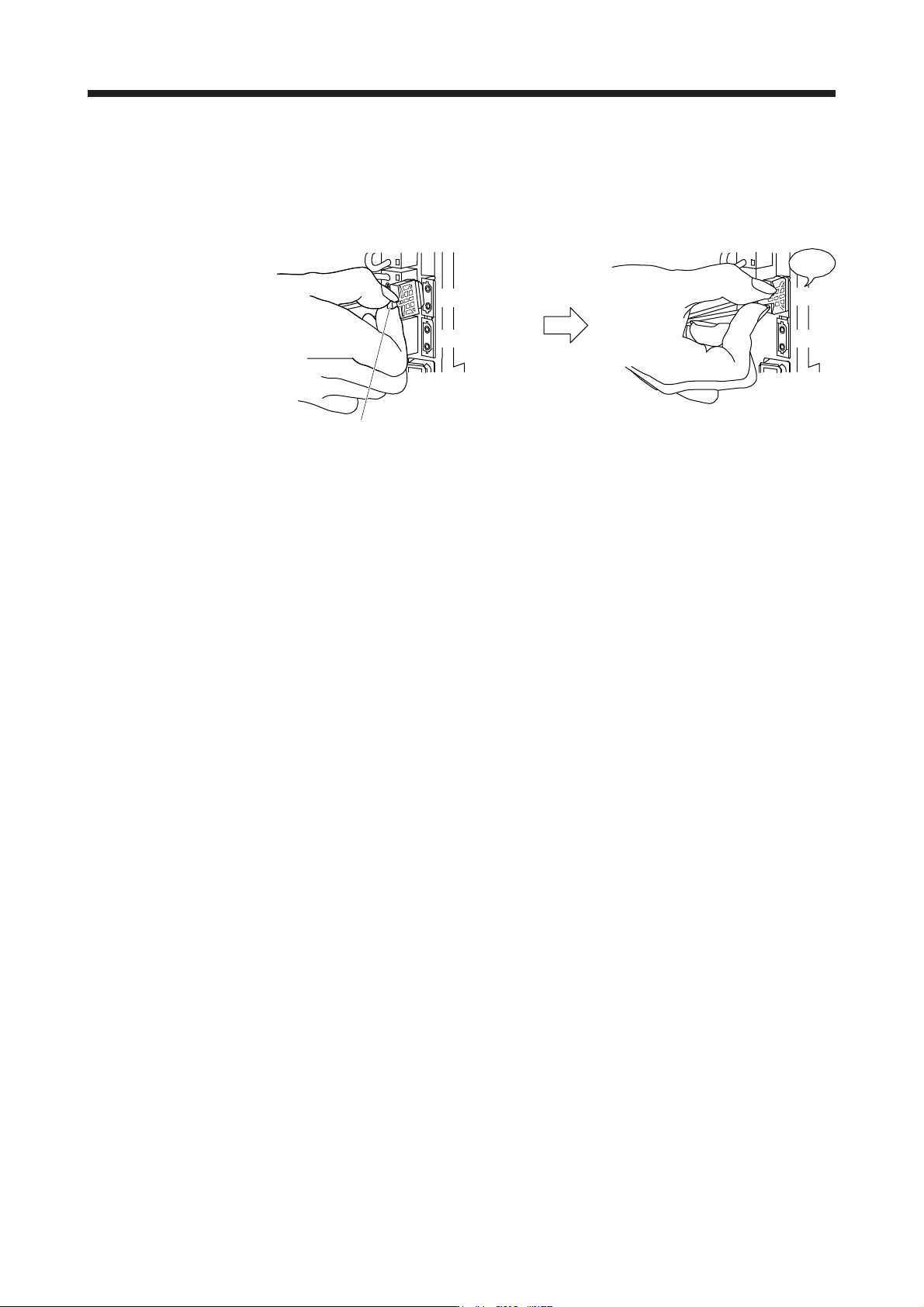
3) With holding a tab of SSCNET III cable connector, make sure to insert it into the CN1A and CN1B
connector of the servo amplifier until you hear the click. If the end face of optical cord tip is dirty,
optical transmission is interrupted and it may cause malfunctions. If it becomes dirty, wipe with a
bonded textile, etc. Do not use solvent such as alcohol.
Click
Tab
Servo amplifier Servo amplifier
CN1A
CN1B
CN1A
CN1B
(b) Disconnection
With holding a tab of SSCNET III cable connector, pull out the connector.
When pulling out the SSCNET III cable from servo amplifier, be sure to put the cap on the connector
parts of servo amplifier to prevent it from becoming dirty. For SSCNET III cable, attach the tube for
protection optical cord's end face on the end of connector.
3. SIGNALS AND WIRING
3 - 41
3.10 Servo motor with an electromagnetic brake
3.10.1 Safety precautions
CAUTION
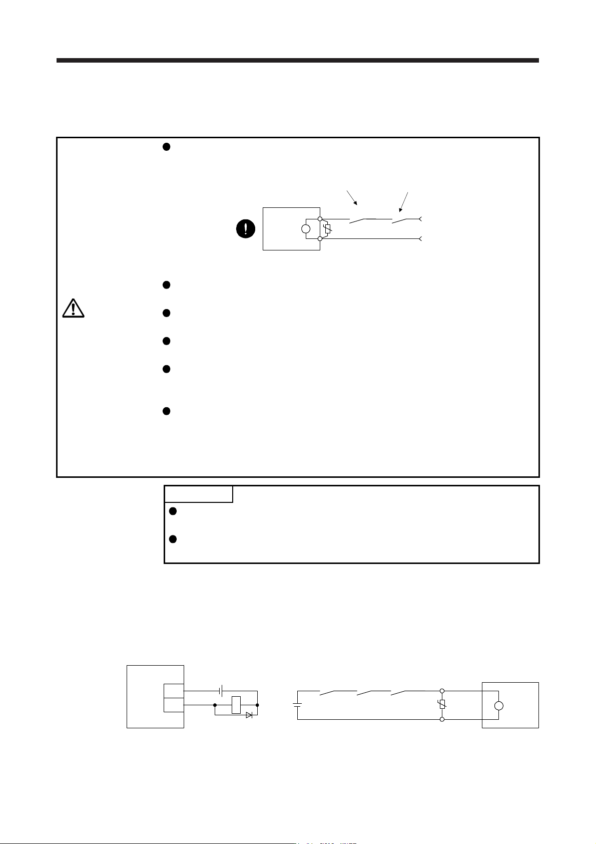
Configure an electromagnetic brake circuit which is interlocked with an external
emergency stop switch.
Servo motor
Electromagnetic brake
B
U
RA
Contacts must be opened when ALM (Malfunction
)
or MBR (Electromagnetic brake interlock) turns off.
24 V DC
Contacts must be opened with th
e
emergency stop switch.
Failure of MBR (Electromagnetic brake interlock) or ALM (Malfunction) may cause
brake malfunction.
The electromagnetic brake is provided for holding purpose and must not be used
for ordinary braking.
Before operating the servo motor, be sure to confirm that the electromagnetic
brake operates properly.
Do not use the 24 V DC interface power supply for the electromagnetic brake.
Always use the power supply designed exclusively for the electromagnetic brake.
Otherwise, it may cause a malfunction.
When using EM2 (Forced stop 2), use MBR (Electromagnetic brake interlock) for
operating the electromagnetic brake. Operating the electromagnetic brake without
using MBR during deceleration to a stop will saturate servo motor torques at the
maximum value due to brake torque of the electromagnetic brake. This can result
in delay of the deceleration to a stop from a set value.
POINT
Refer to "Servo Motor Instruction Manual (Vol. 3)" for specifications such as the
power supply capacity and operation delay time of the electromagnetic brake.
Refer to "Servo Motor Instruction Manual (Vol. 3)" for the selection of a surge
absorber for the electromagnetic brake.
Note the following when the servo motor with an electromagnetic brake is used.
1) The electromagnetic brake will operate when the power (24 V DC) turns off.
2) Turn off the servo-on command after the servo motor stopped.
(1) Connection diagram
B2
B1
U
B
Servo motor
24 V DC
ALM
(Malfunction)
(Note 2)
MBR(Note 2)
RA1
(Note 1)
Servo amplifier
MBR
DOCOM
RA1
(Note 3)
24 V DC
Note 1. Create the circuit in order to shut off b
y
interlockin
g
with the emer
g
enc
y
stop switch.
2. Failure of MBR or ALM ma
y
cause brake malfunction.
3. Do not use the 24 V DC interface power suppl
y
for the electroma
g
netic brake.