sh030106u.pdf - 第119页
3. SIG NALS A ND WIRI NG 3 - 42 (2) Setting In [Pr. PC 02 El ectroma gnetic br ake seq uence out put], set a d elay t ime (Tb) from MBR (El ectroma gnetic brake interloc k) off to base circ uit shut-off at a servo-off as…
3. SIGNALS AND WIRING
3 - 41
3.10 Servo motor with an electromagnetic brake
3.10.1 Safety precautions
CAUTION
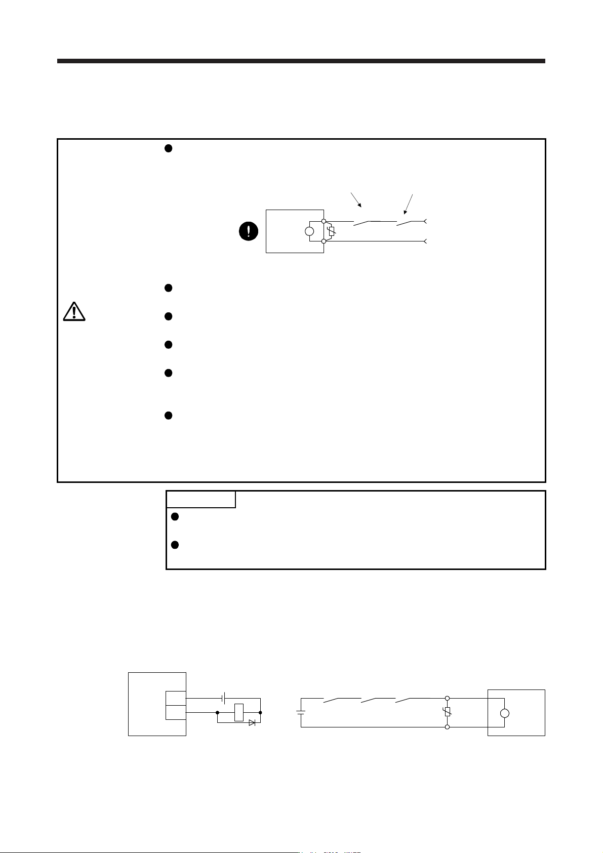
Configure an electromagnetic brake circuit which is interlocked with an external
emergency stop switch.
Servo motor
Electromagnetic brake
B
U
RA
Contacts must be opened when ALM (Malfunction
)
or MBR (Electromagnetic brake interlock) turns off.
24 V DC
Contacts must be opened with th
e
emergency stop switch.
Failure of MBR (Electromagnetic brake interlock) or ALM (Malfunction) may cause
brake malfunction.
The electromagnetic brake is provided for holding purpose and must not be used
for ordinary braking.
Before operating the servo motor, be sure to confirm that the electromagnetic
brake operates properly.
Do not use the 24 V DC interface power supply for the electromagnetic brake.
Always use the power supply designed exclusively for the electromagnetic brake.
Otherwise, it may cause a malfunction.
When using EM2 (Forced stop 2), use MBR (Electromagnetic brake interlock) for
operating the electromagnetic brake. Operating the electromagnetic brake without
using MBR during deceleration to a stop will saturate servo motor torques at the
maximum value due to brake torque of the electromagnetic brake. This can result
in delay of the deceleration to a stop from a set value.
POINT
Refer to "Servo Motor Instruction Manual (Vol. 3)" for specifications such as the
power supply capacity and operation delay time of the electromagnetic brake.
Refer to "Servo Motor Instruction Manual (Vol. 3)" for the selection of a surge
absorber for the electromagnetic brake.
Note the following when the servo motor with an electromagnetic brake is used.
1) The electromagnetic brake will operate when the power (24 V DC) turns off.
2) Turn off the servo-on command after the servo motor stopped.
(1) Connection diagram
B2
B1
U
B
Servo motor
24 V DC
ALM
(Malfunction)
(Note 2)
MBR(Note 2)
RA1
(Note 1)
Servo amplifier
MBR
DOCOM
RA1
(Note 3)
24 V DC
Note 1. Create the circuit in order to shut off b
y
interlockin
g
with the emer
g
enc
y
stop switch.
2. Failure of MBR or ALM ma
y
cause brake malfunction.
3. Do not use the 24 V DC interface power suppl
y
for the electroma
g
netic brake.
3. SIGNALS AND WIRING
3 - 42
(2) Setting
In [Pr. PC02 Electromagnetic brake sequence output], set a delay time (Tb) from MBR (Electromagnetic
brake interlock) off to base circuit shut-off at a servo-off as in the timing chart in section 3.10.2.
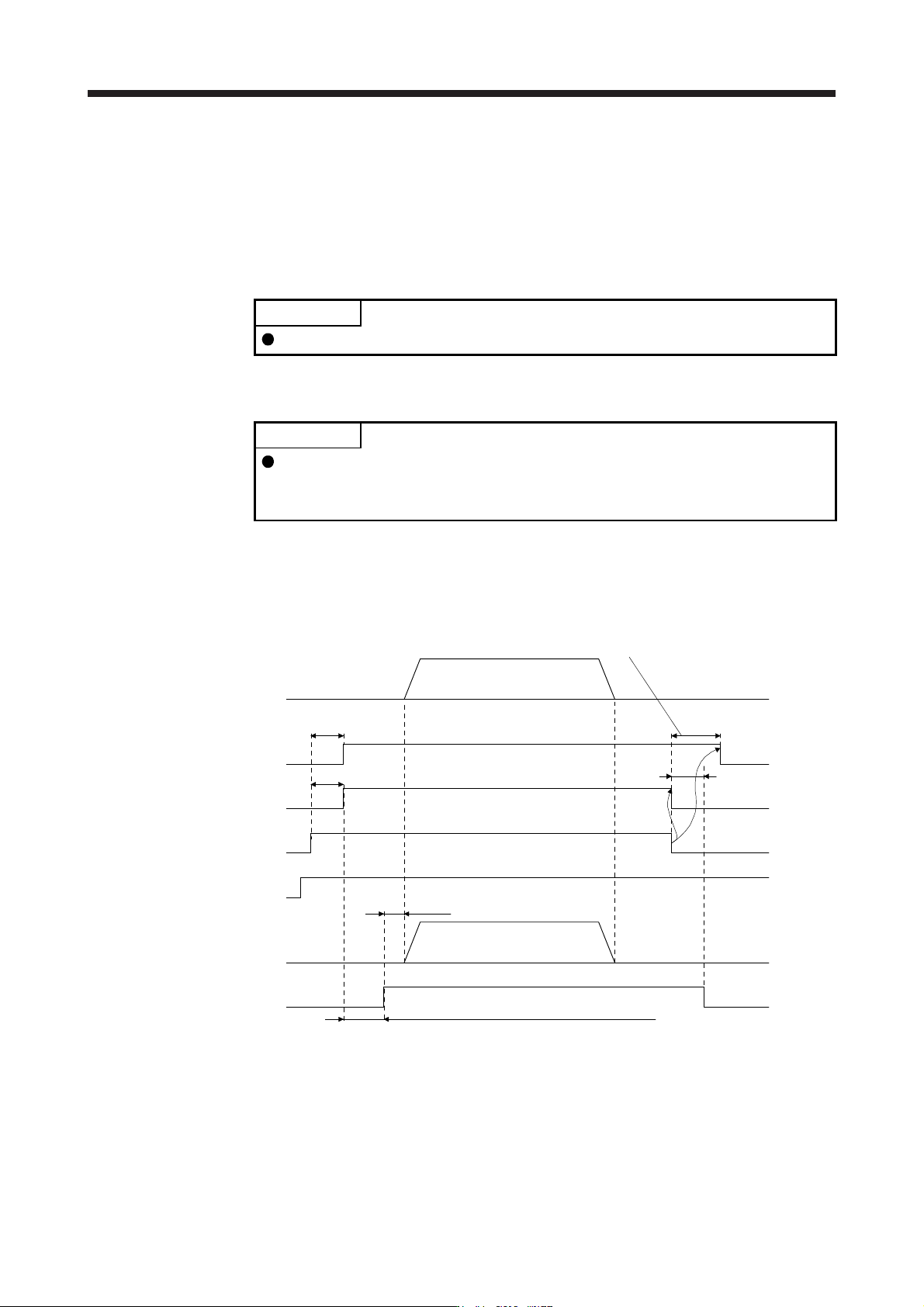
3.10.2 Timing chart
(1) When you use the forced stop deceleration function
POINT
To enable the function, set "2 _ _ _ (initial value)" in [Pr. PA04].
(a) Servo-on command (from controller) on/off
POINT
Keep the ready-on command (from controller) on while the servo-on command
(from controller) is off. When the ready-off command (from controller) is off, Tb
[Pr. PC02 Electromagnetic brake sequence output] does not function.
When servo-on command is turned off, the servo lock will be released after Tb [ms], and the servo
motor will coast. If the electromagnetic brake is enabled during servo-lock, the brake life may be
shorter. Therefore, set Tb about 1.5 times of the minimum delay time where the moving part will not
drop down for a vertical axis system, etc.
(Note 1)
ON
OFF
ON
OFF
0 r/min
ON
OFF
(Note 3)
0 r/min
ON
OFF
MBR
(Electromagnetic
brake interlock)
Base circuit
Servo motor speed
Operation delay time
of the electromagnetic
brake
Ready-on command
(from controller)
Release
Activate
Operation command
(from controller)
Electromagnetic
brake
Servo-on command
(from controller)
Tb [Pr. PC02 Electromagnetic brake sequence output]
Release delay time and external relay, etc. (Note 2)
Approx. 95 ms
Approx. 95 ms
Note 1. ON: Electromagnetic brake is not activated.
OFF: Electroma
g
netic brake is activated.
2. Electromagnetic brake is released after delaying for the release delay time of electromagnetic brake and operation time of
external circuit rela
y
. For the release dela
y
time of electroma
g
netic brake, refer to "Servo Motor Instruction Manual
(
Vol. 3
)
".
3. Give the operation command from the controller after the electroma
g
netic brake is released.
3. SIGNALS AND WIRING
3 - 43
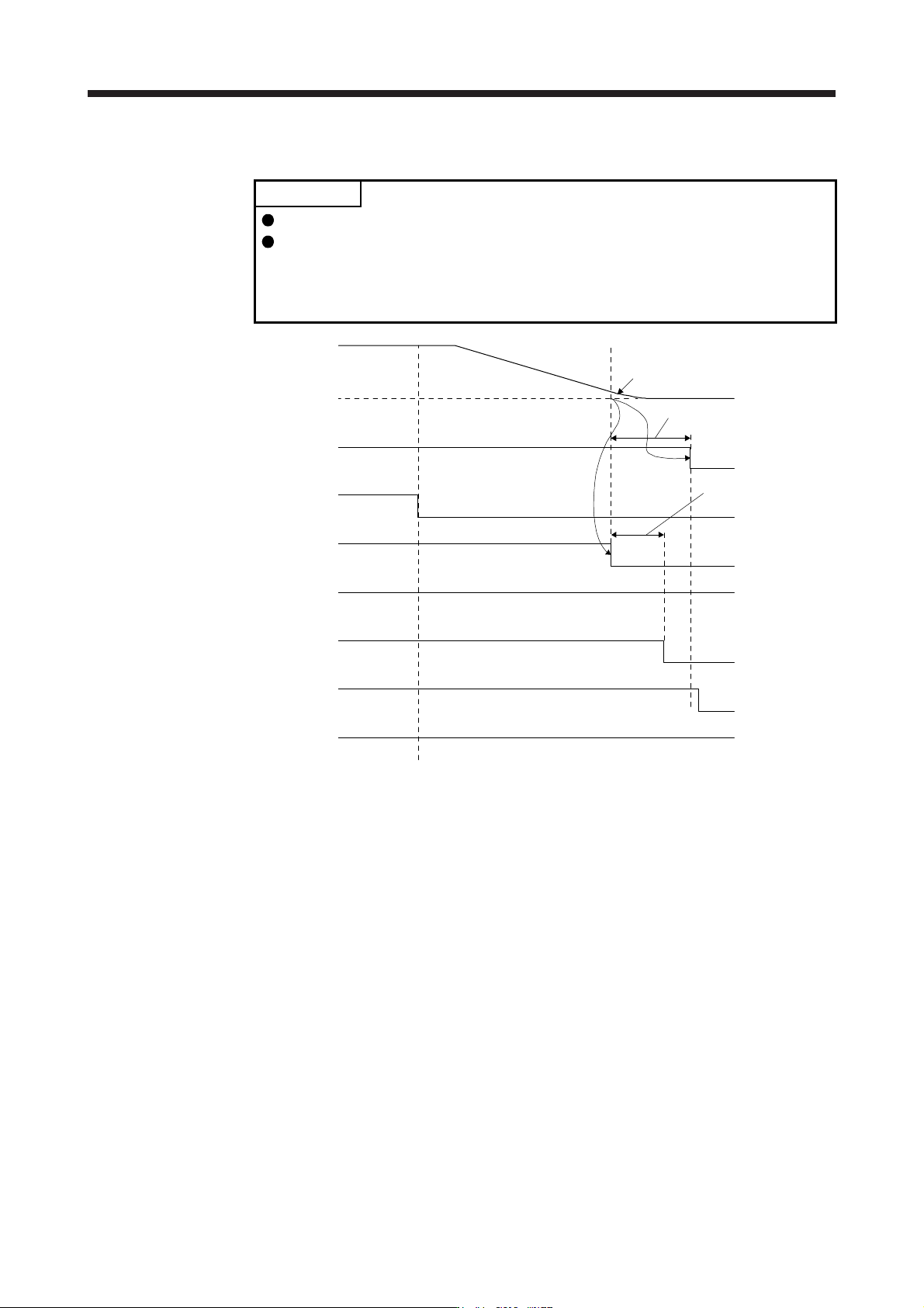
(b) Off/on of the forced stop command (from controller) or EM2 (Forced stop 2)
POINT
In the torque control mode, the forced stop deceleration function is not available.
Keep the servo-on command (from controller) and ready-on command (from
controller) on while the forced stop command (from controller) or the EM2
(Forced stop 2) is off. When the ready-off command (from controller) is off, Tb
[Pr. PC02 Electromagnetic brake sequence output] does not function.
MBR
(Electromagnetic
brake interlock)
ON
ALM (Malfunction)
ON (no alarm)
OFF (alarm)
Base circuit
(Energy supply to
the servo motor)
ON
(Note 1)
OFF
0 r/min
Servo motor speed
Model speed command 0
and equal to or less than
zero speed (Note 2)
Disabled (ON)
Enabled (OFF)
OFF
ON
ON
OFF
Release
Activate
OFF
Electromagnetic brake
Forced stop command
(from controller) or EM2
(Forced stop 2)
Tb [Pr. PC02 Electromagnetic
brake sequence output]
Operation delay time
of the electromagnetic
brake
Ready-on command
(from controller)
Servo-on command
(from controller)
Note 1. ON: Electromagnetic brake is not activated.
OFF: Electroma
g
netic brake is activated.
2. The model speed command is a speed command generated in the servo amplifier for forced stop deceleration of the servo
motor.