sh030106u.pdf - 第127页
4. STA RTUP 4 - 2 4.1 Switch ing power o n for the f irst time When switch ing po wer on for the f irst time, follow th is sec tion to mak e a startup. 4.1.1 St artup pr ocedure Wiring check Surrounding environment check…
4. STARTUP
4 - 1
4. STARTUP
WARNING
When executing a test run, follow the notice and procedures in this instruction
manual. Otherwise, it may cause a malfunction, damage to the machine, or injury.
Do not operate the switches with wet hands. Otherwise, it may cause an electric
shock.
CAUTION
Before starting operation, check the parameters. Improper settings may cause
some machines to operate unexpectedly.
The servo amplifier heat sink, regenerative resistor, servo motor, etc., may be hot
while the power is on and for some time after power-off. Take safety measures
such as providing covers to avoid accidentally touching them by hands and parts
such as cables.
During operation, never touch the rotor of the servo motor. Otherwise, it may
cause injury.
Before wiring, switch operation, etc., eliminate static electricity. Otherwise, it may
cause a malfunction.
POINT
When you use a linear servo motor, replace the following words in the left to the
words in the right.
Load to motor inertia ratio → Load to motor mass ratio
Torque → Thrust
(Servo motor) speed → (Linear servo motor) speed
4. STARTUP
4 - 2
4.1 Switching power on for the first time
When switching power on for the first time, follow this section to make a startup.
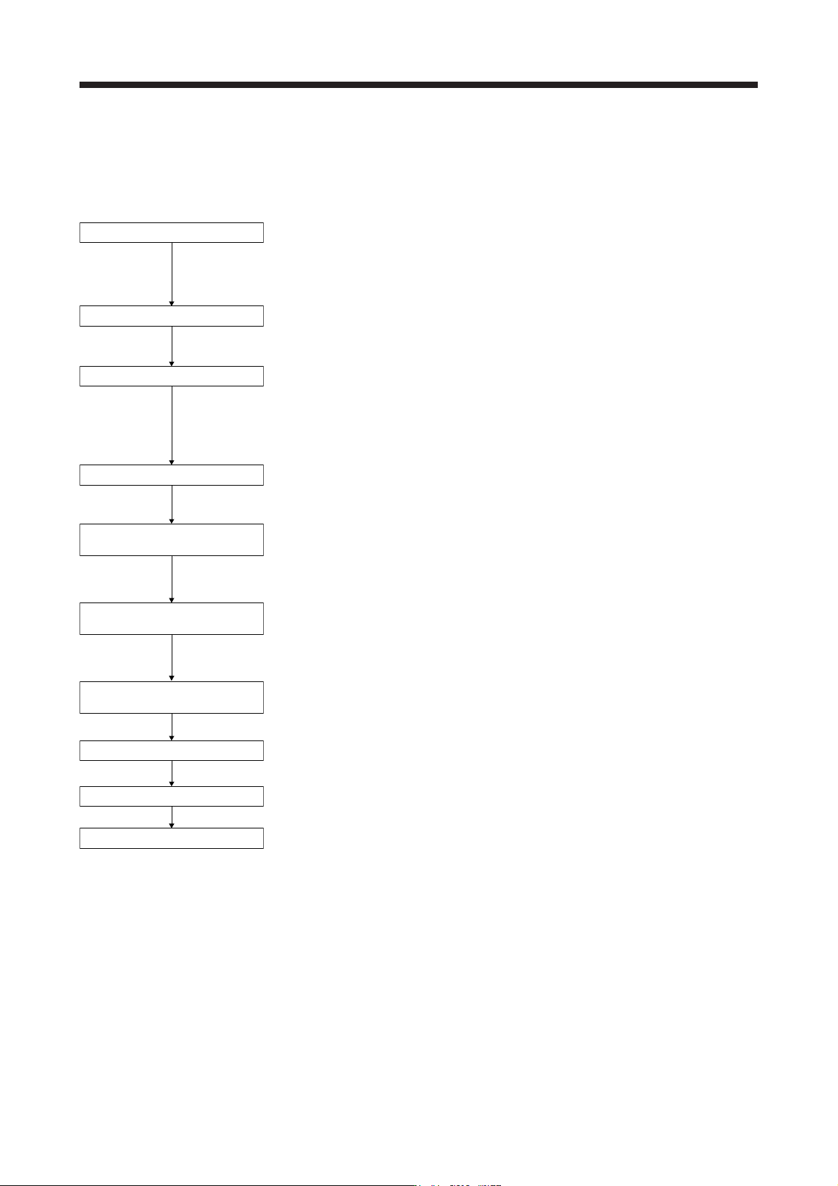
4.1.1 Startup procedure
Wiring check
Surrounding environment check
Axis No. settings
Parameter setting
Test operation of the servo motor
alone in test operation mode
Test operation of the servo
motor alone by commands
Test operation with the servo
motor and machine connected
Gain adjustment
Actual operation
Stop
Check whether the servo amplifier and servo motor are wired correctly using
visual inspection, DO forced output function (section 4.5.1), etc. (Refer to
section 4.1.2.)
Check the surrounding environment of the servo amplifier and servo motor.
(Refer to section 4.1.3.)
Confirm that the control axis No. set with the auxiliary axis number setting
switches (SW2-3 and SW2-4) and with the axis selection rotary switch
(SW1) match the control axis No. set with the servo system controller. (Refer
to section 4.3.1 (3).)
Set the parameters as necessary, such as the used operation mode and
regenerative option selection. (Refer to chapter 5.)
For the test operation, with the servo motor disconnected from the machine
and operated at the speed as low as possible, check whether the servo
motor rotates correctly. (Refer to section 4.5.)
For the test operation with the servo motor disconnected from the machine
and operated at the speed as low as possible, give commands to the servo
amplifier and check whether the servo motor rotates correctly.
After connecting the servo motor with the machine, check machine motions
with sending operation commands from the servo system controller.
Make gain adjustment to optimize the machine motions. (Refer to chapter 6.)
Stop giving commands and stop operation.
4. STARTUP
4 - 3
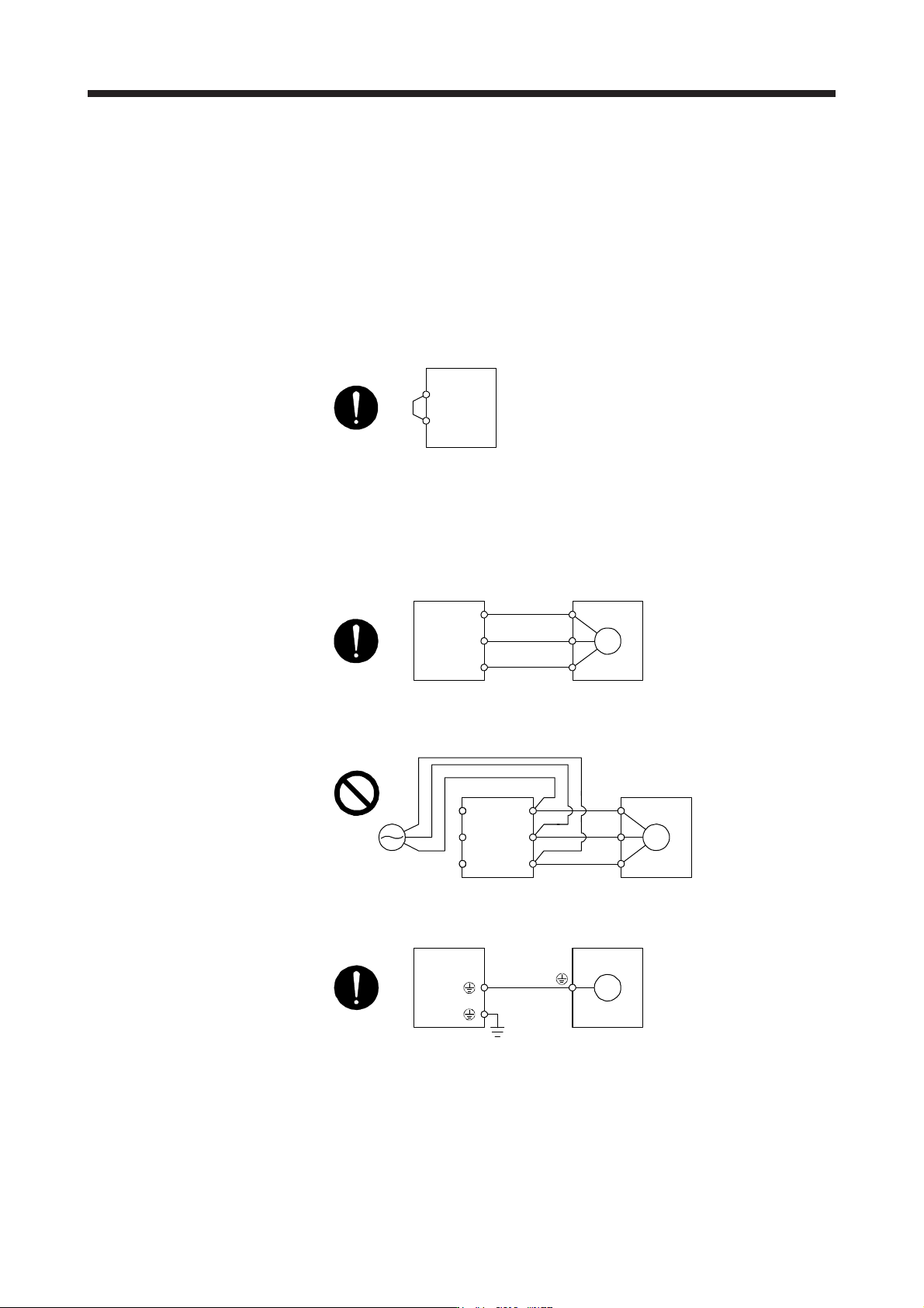
4.1.2 Wiring check
(1) Power supply system wiring
Before switching on the main circuit and control circuit power supplies, check the following items.
(a) Power supply system wiring
1) The power supplied to the power input terminals (L1/L2/L3/L11/L21) of the servo amplifier should
satisfy the defined specifications. (Refer to section 1.3.)
2) When the power factor improving DC reactor is not used, between P3 and P4 should be
connected.
P3
P4
Servo amplifier
(Note)
Note. The 100 V class servo amplifiers do not have P3 and P4.
(b) Connection of servo amplifier and servo motor
1) The servo amplifier power output (U/V/W) should match in phase with the servo motor power
input terminals (U/V/W).
Servo amplifier Servo motor
M
U
V
W
U
V
W
2) The power supplied to the servo amplifier should not be connected to the servo motor power
terminals (U/V/W). Otherwise, the servo amplifier and servo motor will malfunction.
Servo amplifier Servo motor
M
U
V
W
U
V
W
L1
L2
L3
3) The grounding terminal of the servo motor is connected to the PE terminal of the servo amplifier.
Servo amplifie
r
Servo moto
r
M
4) The CN2 connector of the servo amplifier should be connected to the encoder of the servo motor
securely using the encoder cable.