sh030106u.pdf - 第136页
4. STA RTUP 4 - 11 4.3.2 Scr olling disp lay (1) Normal display When there is no a larm, the ax is No. an d blank are di splayed in r otat ion. Status (1 digit) Axis No. (2 digits) "b" "C" "d&quo…
4. STARTUP
4 - 10
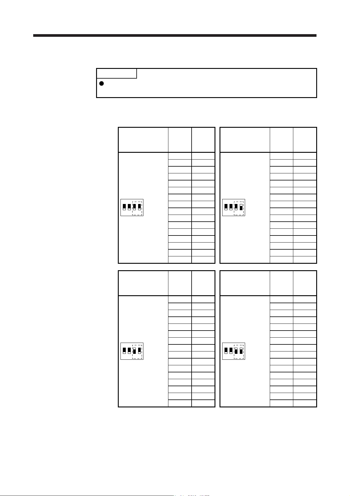
(c) Switch combination list for the control axis No. setting
POINT
Set control axis Nos. for one system. For details of the control axis No., refer to
the servo system controller user's manual.
The following lists show the setting combinations of the auxiliary axis number setting switches and
the axis selection rotary switch.
Auxiliary axis number
setting switch
Axis
selection
rotary
switch
Control
axis No.
Auxiliary axis number
setting switch
Axis
selection
rotary
switch
Control
axis No.
1
ON
2 3 4
0 1
1
ON
2 3 4
0 17
1 2 1 18
2 3 2 19
3 4 3 20
4 5 4 21
5 6 5 22
6 7 6 23
7 8 7 24
8 9 8 25
9 10 9 26
A 11 A 27
B 12 B 28
C 13 C 29
D 14 D 30
E 15 E 31
F 16 F 32
Auxiliary axis number
setting switch
Axis
selection
rotary
switch
Control
axis No.
Auxiliary axis number
setting switch
Axis
selection
rotary
switch
Control
axis No.
1
ON
2 3 4
0 33
1
ON
2 3 4
0 49
1 34 1 50
2 35 2 51
3 36 3 52
4 37 4 53
5 38 5 54
6 39 6 55
7 40 7 56
8 41 8 57
9 42 9 58
A 43 A 59
B 44 B 60
C 45 C 61
D 46 D 62
E 47 E 63
F 48 F 64
4. STARTUP
4 - 11
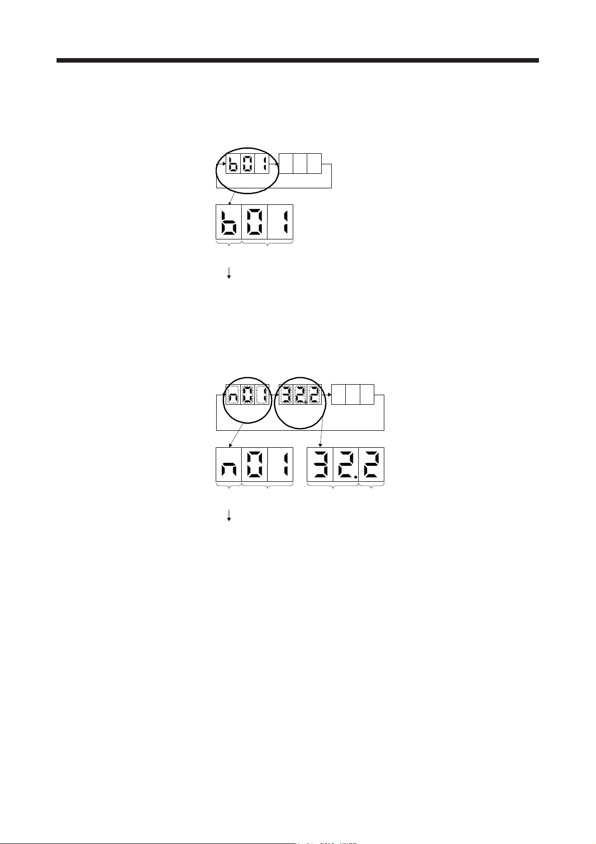
4.3.2 Scrolling display
(1) Normal display
When there is no alarm, the axis No. and blank are displayed in rotation.
Status
(1 digit)
Axis No.
(2 digits)
"b"
"C"
"d"
: Indicates ready-off and servo-off status.
: Indicates ready-on and servo-off status.
: Indicates ready-on and servo-on status.
Status
A
fter 1.6 s
Blank
After 0.2 s
(2) Alarm display
When an alarm occurs, the alarm number (two digits) and the alarm detail (one digit) are displayed
following the status display. For example, the following shows when [AL. 32 Overcurrent] is occurring.
Status
After 0.8 s
Alarm No.
After 0.8 s
Blank
After 0.2 s
Status
(1 digit)
Axis No.
(2 digits)
"n": Indicates that an alarm is occurring.
Alarm detail
(1 digit)
Alarm No.
(2 digits)
4. STARTUP
4 - 12
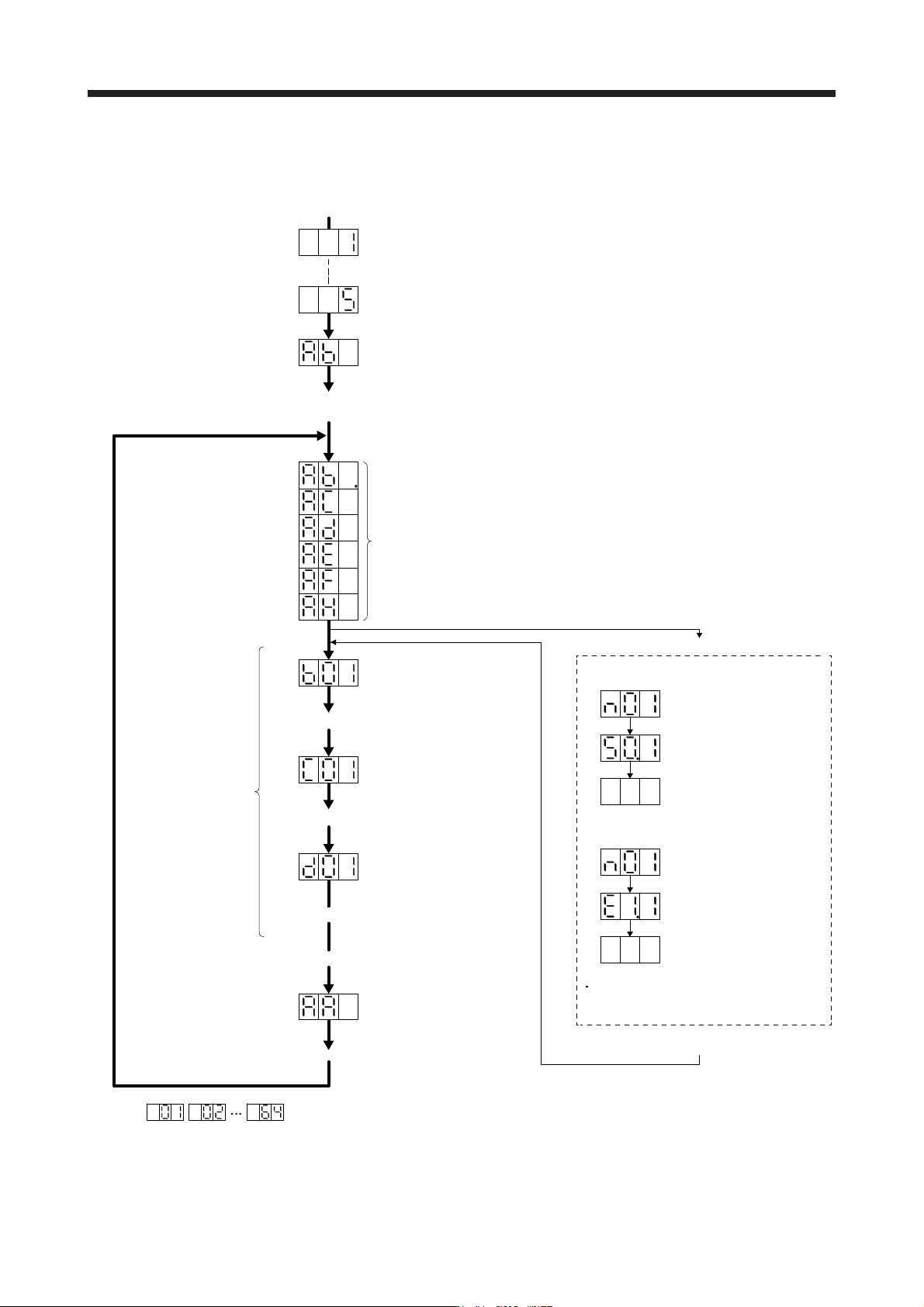
4.3.3 Status display of an axis
(1) Display sequence
The segment of the last 2 digits shows the axis number.
Servo system controller power on
(SSCNET III/H communication begins)
Ready-on
Servo-on
Ordinary operation
Servo system controller power off
Servo system controller power on
When an alarm or a
warning occurs, the
alarm No. or the
warning No. is shown.
Waiting for servo system controller power to switch on
(SSCNET III/H communication)
Ready-on and servo-off
Ready-on and servo-on
(Note)
(Note)
(Note)
When an alarm No. or warning No. is displayed
Axis
No. 1
Axis
No. 2
Axis
No. 64
Initial data communication with the
servo system controller
(initialization communication)
Ready-off and servo-off
Note.
Example:
Blinking
Blinking
After 0.8 s
Blank
After 0.8 s
When [AL. 50 Overload 1]
occurs at axis No. 1
Example:
Blinking
Blinking
After 0.8 s
Blank
After 0.8 s
When [AL. E1 Overload warning 1]
occurs at axis No. 1
During a warning that does not cause
servo-off, the decimal point on the third
digit LED shows the servo-on status.
Servo amplifier power on
System check in progress
Alarm reset or warning cleared