sh030106u.pdf - 第142页
4. STA RTUP 4 - 17 (2) Operation pr ocedur e 1) Turn off the pow er. 2) Turn " ON (up)" SW2-1. Set SW2-1 to "ON (up)". ON 12 34 1 ON 2 3 4 Turning " ON (up)" SW2-1 during power- on will no t…

4. STARTUP
4 - 16
(b) Positioning operation
Positioning operation can be performed without using the servo system controller. Use this operation
with the forced stop reset. This operation may be used independently of whether the servo is on or
off and whether the servo system controller is connected or not.
Exercise control on the positioning operation screen of MR Configurator2.
1) Operation pattern
Item initial value Setting range
Travel distance [pulse] 4000 0 to 99999999
Speed [r/min] 200 0 to max. speed
Acceleration/deceleration
time constant [ms]
1000 0 to 50000
Repeat pattern
Fwd. rot. (CCW) to
rev. rot. (CW)
Fwd. rot. (CCW) to rev. rot. (CW)
Fwd. rot. (CCW) to fwd. rot. (CCW)
Rev. rot. (CW) to fwd. rot. (CCW)
Rev. rot. (CW) to rev. rot. (CW)
Dwell time [s] 2.0 0.1 to 50.0
Number of repeats [time] 1 1 to 9999
2) Operation method
Operation Screen control
Forward rotation start Click "Forward".
Reverse rotation start Click "Reverse".
Pause Click "Pause".
Stop Click "Stop".
Forced stop Click "Forced stop".
(c) Program operation
Positioning operation can be performed in two or more operation patterns combined, without using
the servo system controller. Use this operation with the forced stop reset. This operation may be
used independently of whether the servo is on or off and whether the servo system controller is
connected or not.
Exercise control on the program operation screen of MR Configurator2. For details, refer to Help of
MR Configurator2.
Operation Screen control
Start Click "Start".
Pause Click "Pause".
Stop Click "Stop".
Forced stop Click "Forced stop".
(d) Output signal (DO) forced output
Output signals can be switched on/off forcibly independently of the servo status. Use this function for
output signal wiring check, etc. Exercise control on the DO forced output screen of MR
Configurator2.
4. STARTUP
4 - 17
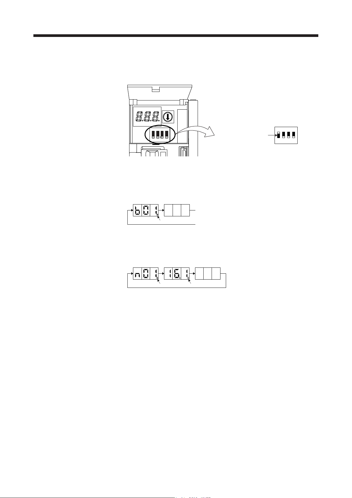
(2) Operation procedure
1) Turn off the power.
2) Turn "ON (up)" SW2-1.
Set SW2-1 to "ON (up)".
ON
1234
1
ON
2 3 4
Turning "ON (up)" SW2-1 during power-on will not start the test operation mode.
3) Turn on the servo amplifier.
When initialization is completed, the decimal point on the first digit will blink.
After 1.6 s
After 0.2 s
Blinking
When an alarm or warning also occurs during the test operation, the decimal point on the first
digit will blink as follows.
After 0.8 s After 0.8 s
After 0.2 s
Blinking Blinking
4) Start operation with the personal computer.
4. STARTUP
4 - 18
4.5.2 Motor-less operation in controller
POINT
Use motor-less operation which is available by making the servo system
controller servo parameter setting.
Connect the servo system controller to the servo amplifier before the motor-less
operation.
The motor-less operation is not used in the fully closed loop control mode, linear
servo motor control mode, and DD motor control mode.
(1) Motor-less operation
Without connecting the servo motor to the servo amplifier, output signals or status displays can be
provided in response to the servo system controller commands as if the servo motor is actually running.
This operation may be used to check the servo system controller sequence. Use this operation with the
forced stop reset. Use this operation with the servo amplifier connected to the servo system controller.
To stop the motor-less operation, set the motor-less operation selection to "Disable" in the servo
parameter setting of the servo system controller. When the power supply is turned on next time, motor-
less operation will be disabled.
(a) Load conditions
Load item Condition
Load torque 0
Load to motor inertia ratio [Pr. PB06 Load to motor inertia ratio/load to motor mass ratio]
(b) Alarms
The following alarms and warning do not occur. However, the other alarms and warnings occur as
when the servo motor is connected.
[AL. 16 Encoder initial communication error 1]
[AL. 1E Encoder initial communication error 2]
[AL. 1F Encoder initial communication error 3]
[AL. 20 Encoder normal communication error 1]
[AL. 21 Encoder normal communication error 2]
[AL. 25 Absolute position erased]
[AL. 92 Battery cable disconnection warning]
[AL. 9F Battery warning]