sh030106u.pdf - 第149页
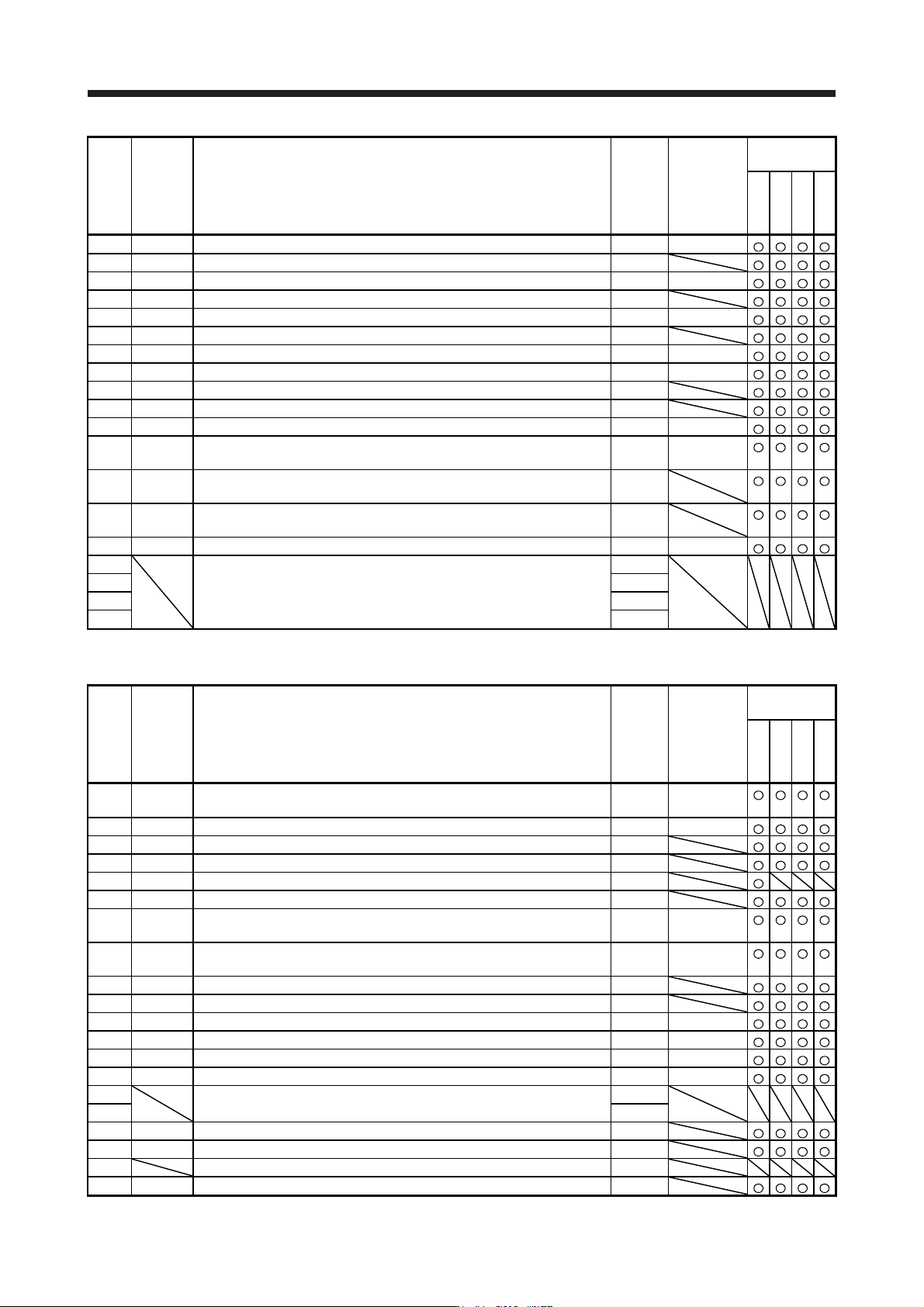
5. PARAMETE RS 5 - 4 No. Symbol Name Initial value Unit Operation mode Standard Full. Lin. D.D. PB46 NH3 Mac hine resonance suppress ion filter 3 4500 [ Hz] PB47 NHQ3 Not ch shape sel ection 3 0000h PB48 NH4 Mac hine res…
5. PARAMETERS
5 - 3
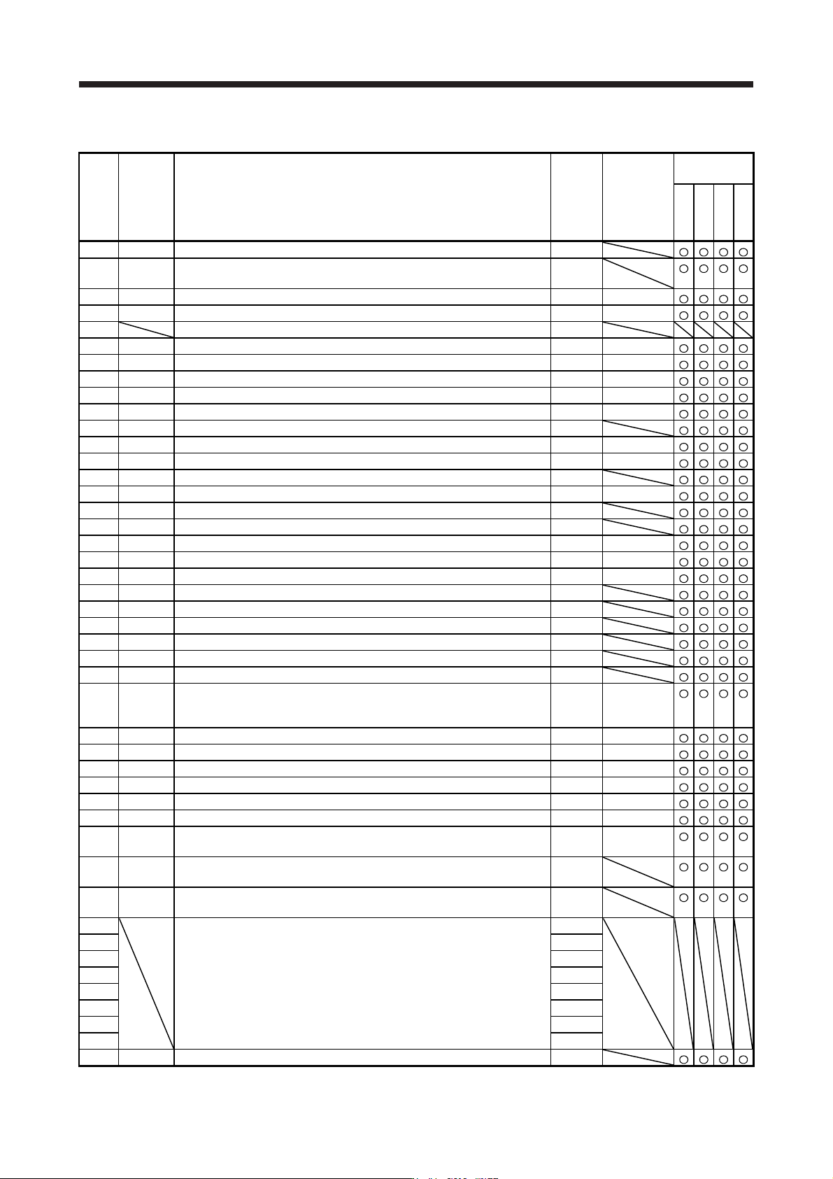
5.1.2 Gain/filter setting parameters ([Pr. PB_ _ ])
No. Symbol Name
Initial
value
Unit
Operation
mode
Standard
Full.
Lin.
D.D.
PB01 FILT Adaptive tuning mode (adaptive filter II) 0000h
PB02 VRFT
Vibration suppression control tuning mode (advanced vibration
suppression control II)
0000h
PB03 TFBGN Torque feedback loop gain 18000 [rad/s]
PB04 FFC Feed forward gain 0 [%]
PB05 For manufacturer setting 500
PB06 GD2 Load to motor inertia ratio/load to motor mass ratio 7.00 [Multiplier]
PB07 PG1 Model loop gain 15.0 [rad/s]
PB08 PG2 Position loop gain 37.0 [rad/s]
PB09 VG2 Speed loop gain 823 [rad/s]
PB10 VIC Speed integral compensation 33.7 [ms]
PB11 VDC Speed differential compensation 980
PB12 OVA Overshoot amount compensation 0 [%]
PB13 NH1 Machine resonance suppression filter 1 4500 [Hz]
PB14 NHQ1 Notch shape selection 1 0000h
PB15 NH2 Machine resonance suppression filter 2 4500 [Hz]
PB16 NHQ2 Notch shape selection 2 0000h
PB17 NHF Shaft resonance suppression filter 0000h
PB18 LPF Low-pass filter setting 3141 [rad/s]
PB19 VRF11 Vibration suppression control 1 - Vibration frequency 100.0 [Hz]
PB20 VRF12 Vibration suppression control 1 - Resonance frequency 100.0 [Hz]
PB21 VRF13 Vibration suppression control 1 - Vibration frequency damping 0.00
PB22 VRF14 Vibration suppression control 1 - Resonance frequency damping 0.00
PB23 VFBF Low-pass filter selection 0000h
PB24 *MVS Slight vibration suppression control 0000h
PB25 *BOP1 Function selection B-1 0000h
PB26 *CDP Gain switching function 0000h
PB27 CDL Gain switching condition 10
[kpulse/s]/
[pulse]/
[r/min]
PB28 CDT Gain switching time constant 1 [ms]
PB29 GD2B Load to motor inertia ratio/load to motor mass ratio after gain switching 7.00 [Multiplier]
PB30 PG2B Position loop gain after gain switching 0.0 [rad/s]
PB31 VG2B Speed loop gain after gain switching 0 [rad/s]
PB32 VICB Speed integral compensation after gain switching 0.0 [ms]
PB33 VRF11B Vibration suppression control 1 - Vibration frequency after gain switching 0.0 [Hz]
PB34 VRF12B
Vibration suppression control 1 - Resonance frequency after gain
switching
0.0 [Hz]
PB35 VRF13B
Vibration suppression control 1 - Vibration frequency damping after gain
switching
0.00
PB36 VRF14B
Vibration suppression control 1 - Resonance frequency damping after
gain switching
0.00
PB37 For manufacturer setting 1600
PB38 0.00
PB39 0.00
PB40 0.00
PB41 0
PB42 0
PB43 0000h
PB44 0.00
PB45 CNHF Command notch filter 0000h
5. PARAMETERS
5 - 4
No. Symbol Name
Initial
value
Unit
Operation
mode
Standard
Full.
Lin.
D.D.
PB46 NH3 Machine resonance suppression filter 3 4500 [Hz]
PB47 NHQ3 Notch shape selection 3 0000h
PB48 NH4 Machine resonance suppression filter 4 4500 [Hz]
PB49 NHQ4 Notch shape selection 4 0000h
PB50 NH5 Machine resonance suppression filter 5 4500 [Hz]
PB51 NHQ5 Notch shape selection 5 0000h
PB52 VRF21 Vibration suppression control 2 - Vibration frequency 100.0 [Hz]
PB53 VRF22 Vibration suppression control 2 - Resonance frequency 100.0 [Hz]
PB54 VRF23 Vibration suppression control 2 - Vibration frequency damping 0.00
PB55 VRF24 Vibration suppression control 2 - Resonance frequency damping 0.00
PB56 VRF21B Vibration suppression control 2 - Vibration frequency after gain switching 0.0 [Hz]
PB57 VRF22B
Vibration suppression control 2 - Resonance frequency after gain
switching
0.0 [Hz]
PB58 VRF23B
Vibration suppression control 2 - Vibration frequency damping after gain
switching
0.00
PB59 VRF24B
Vibration suppression control 2 - Resonance frequency damping after
gain switching
0.00
PB60 PG1B Model loop gain after gain switching 0.0 [rad/s]
PB61 For manufacturer setting 0.0
PB62 0000h
PB63 0000h
PB64 0000h
5.1.3 Extension setting parameters ([Pr. PC_ _ ])
No. Symbol Name
Initial
value
Unit
Operation
mode
Standard
Full.
Lin.
D.D.
PC01 ERZ Error excessive alarm level 0
[rev]/
[mm]
PC02 MBR Electromagnetic brake sequence output 0 [ms]
PC03 *ENRS Encoder output pulse selection 0000h
PC04 **COP1 Function selection C-1 0000h
PC05 **COP2 Function selection C-2 0000h
PC06 *COP3 Function selection C-3 0000h
PC07 ZSP Zero speed 50
[r/min]/
[mm/s]
PC08 OSL Overspeed alarm detection level 0
[r/min]/
[mm/s]
PC09 MOD1 Analog monitor 1 output 0000h
PC10 MOD2 Analog monitor 2 output 0001h
PC11 MO1 Analog monitor 1 offset 0 [mV]
PC12 MO2 Analog monitor 2 offset 0 [mV]
PC13 MOSDL Analog monitor - Feedback position output standard data - Low 0 [pulse]
PC14 MOSDH Analog monitor - Feedback position output standard data - High 0
[10000 pulses]
PC15 For manufacturer setting 0
PC16 0000h
PC17 **COP4 Function selection C-4 0000h
PC18 *COP5 Function selection C-5 0000h
PC19 For manufacturer setting 0000h
PC20 *COP7 Function selection C-7 0000h
5. PARAMETERS
5 - 5
No. Symbol Name
Initial
value
Unit
Operation
mode
Standard
Full.
Lin.
D.D.
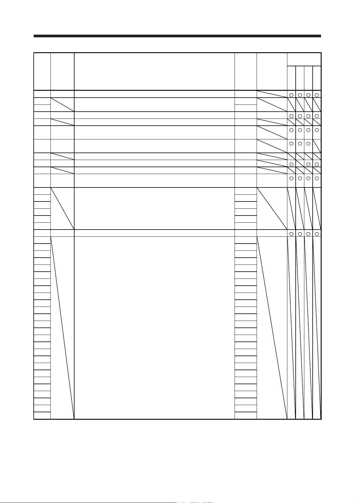
PC21 *BPS Alarm history clear 0000h
PC22 For manufacturer setting 0
PC23 0000h
PC24 RSBR Forced stop deceleration time constant 100 [ms]
PC25 For manufacturer setting 0
PC26 **COP8 Function selection C-8 0000h
(Note
)
PC27 **COP9 Function selection C-9 0000h
(Note
)
PC28 For manufacturer setting 0000h
PC29 *COPB Function selection C-B 0000h
PC30 For manufacturer setting 0
PC31 RSUP1 Vertical axis freefall prevention compensation amount 0 [0.0001 rev]/
[0.01 mm]
PC32 For manufacturer setting 0000h
PC33 0
PC34 100
PC35 0000h
PC36 0000h
PC37 0000h
PC38 ERW Error excessive warning level 0 [rev]/[mm]
PC39 For manufacturer setting 0000h
PC40 0000h
PC41 0000h
PC42 0000h
PC43 0000h
PC44 0000h
PC45 0000h
PC46 0000h
PC47 0000h
PC48 0000h
PC49 0000h
PC50 0000h
PC51 0000h
PC52 0000h
PC53 0000h
PC54 0000h
PC55 0000h
PC56 0000h
PC57 0000h
PC58 0000h
PC59 0000h
PC60 0000h
PC61 0000h
PC62 0000h
PC63 0000h
PC64 0000h
Note. It is available when the scale measurement function is enabled
(
[Pr. PA22] is "1 _ _ _" or "2 _ _ _"
)
.