sh030106u.pdf - 第158页
5. PARAMETE RS 5 - 13 No. Sym bol Name and function Initial value [unit] Setting range PA03 *ABS Absolu te positio n dete ction syste m Set this parameter when using the absolute position detect ion s ystem. Refer to t h…
5. PARAMETERS
5 - 12
No. Symbol Name and function
Initial
value
[unit]
Setting
range
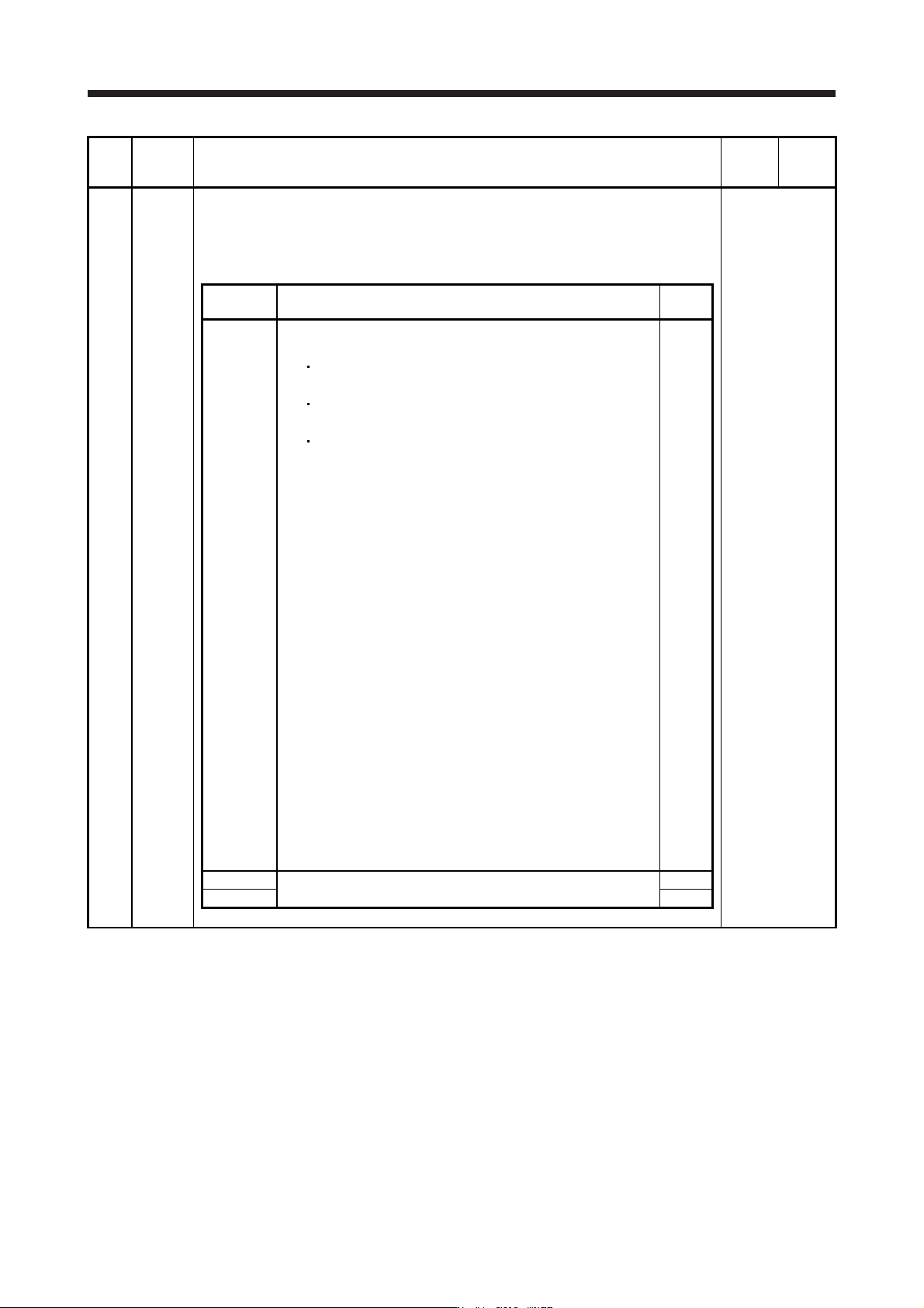
PA02 **REG Regenerative option
Used to select the regenerative option.
Incorrect setting may cause the regenerative option to burn.
If a selected regenerative option is not for use with the servo amplifier, [AL. 37 Parameter
error] occurs.
Refer to the
"Name and
function" column.
Setting
digit
Explanation
Initial
value
_ _ x x Regenerative option selection
00: Regenerative option is not used.
For servo amplifier of 100 W, regenerative resistor is not
used.
For servo amplifier of 0.2 kW to 7 kW, built-in regenerative
resistor is used.
Supplied regenerative resistors or regenerative option is used
with the servo amplifier of 11 kW to 22 kW.
01: FR-RC-(H)/FR-CV-(H)/FR-BU2-(H)/FR-XC-(H)
To use the FR-RC-(H), FR-CV-(H), or FR-XC-(H), select "When
[AL. 10] occurs (_ _ _ 1)" of "Undervoltage alarm detection
method selection" in [Pr. PC20].
02: MR-RB032
03: MR-RB12
04: MR-RB32
05: MR-RB30
06: MR-RB50 (Cooling fan is required.)
08: MR-RB31
09: MR-RB51 (Cooling fan is required.)
0B: MR-RB3N
0C: MR-RB5N (Cooling fan is required.)
80: MR-RB1H-4
81: MR-RB3M-4 (Cooling fan is required.)
82: MR-RB3G-4 (Cooling fan is required.)
83: MR-RB5G-4 (Cooling fan is required.)
84: MR-RB34-4 (Cooling fan is required.)
85: MR-RB54-4 (Cooling fan is required.)
91: MR-RB3U-4 (Cooling fan is required.)
92: MR-RB5U-4 (Cooling fan is required.)
FA: When the supplied regenerative resistors or the regenerative
option is cooled by the cooling fan to increase the ability with
the servo amplifier of 11 kW to 22 kW.
00h
_ x _ _ For manufacturer setting 0h
x _ _ _ 0h
5. PARAMETERS
5 - 13
No. Symbol Name and function
Initial
value
[unit]
Setting
range
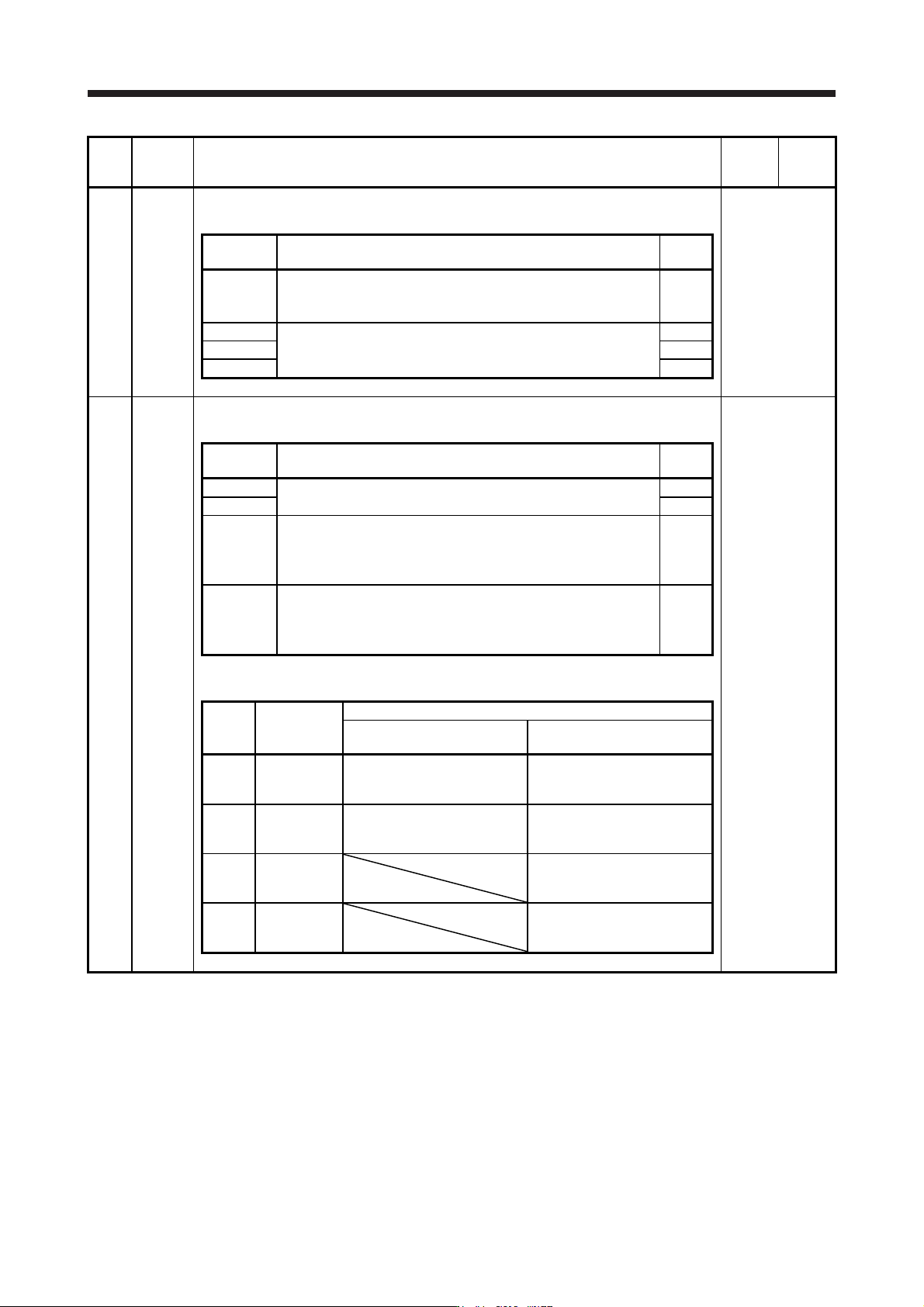
PA03 *ABS Absolute position detection system
Set this parameter when using the absolute position detection system.
Refer to the
"Name and
function" column.
Setting
digit
Explanation
Initial
value
_ _ _ x Absolute position detection system selection
0: Disabled (used in incremental system)
1: Enabled (used in absolute position detection system)
0h
_ _ x _ For manufacturer setting 0h
_ x _ _ 0h
x _ _ _ 0h
PA04 *AOP1 Function selection A-1
This is used to select the forced stop input and forced stop deceleration function.
Refer to the
"Name and
function" column.
Setting
digit
Explanation
Initial
value
_ _ _ x For manufacturer setting 0h
_ _ x _ 0h
_ x _ _ Servo forced stop selection
0: Enabled (The forced stop input EM2 or EM1 is used.)
1: Disabled (The forced stop input EM2 and EM1 are not used.)
Refer to table 5.1 for details.
0h
x _ _ _ Forced stop deceleration function selection
0: Forced stop deceleration function disabled (EM1)
2: Forced stop deceleration function enabled (EM2)
Refer to table 5.1 for details.
2h
Table 5.1 Deceleration method
Setting
value
EM2/EM1
Deceleration method
EM2 or EM1 is off
Controller forced stop is
enabled/Alarm occurred
0 0 _ _ EM1
MBR (Electromagnetic brake
interlock) turns off without the
forced stop deceleration.
MBR (Electromagnetic brake
interlock) turns off without the
forced stop deceleration.
2 0 _ _ EM2
MBR (Electromagnetic brake
interlock) turns off after the
forced stop deceleration.
MBR (Electromagnetic brake
interlock) turns off after the
forced stop deceleration.
0 1 _ _
Not using
EM2 and
EM1
MBR (Electromagnetic brake
interlock) turns off without the
forced stop deceleration.
2 1 _ _
Not using
EM2 and
EM1
MBR (Electromagnetic brake
interlock) turns off after the
forced stop deceleration.
5. PARAMETERS
5 - 14
No. Symbol Name and function
Initial
value
[unit]
Setting
range
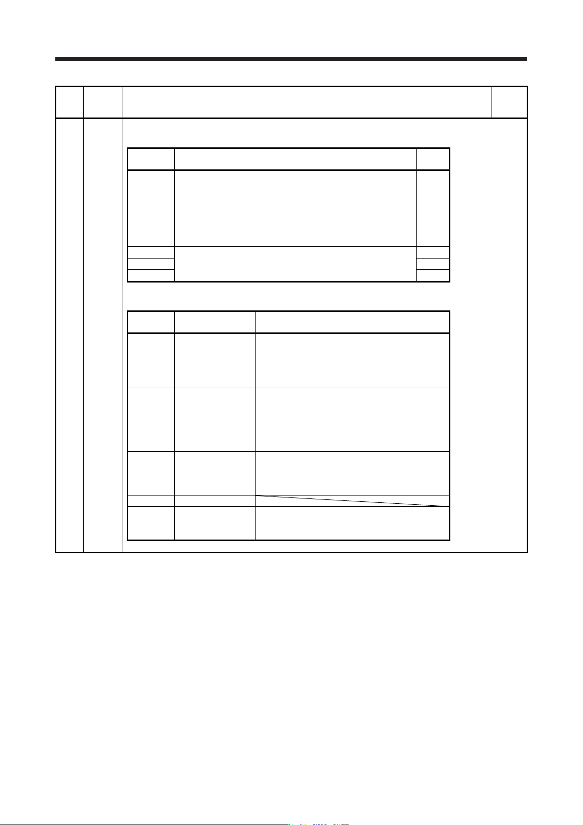
PA08 ATU Auto tuning mode
Select the gain adjustment mode.
Refer to the
"Name and
function" column.
Setting
digit
Explanation
Initial
value
_ _ _ x Gain adjustment mode selection
0: 2 gain adjustment mode 1 (interpolation mode)
1: Auto tuning mode 1
2: Auto tuning mode 2
3: Manual mode
4: 2 gain adjustment mode 2
Refer to table 5.2 for details.
1h
_ _ x _ For manufacturer setting 0h
_ x _ _ 0h
x _ _ _ 0h
Table 5.2 Gain adjustment mode selection
Setting
value
Gain adjustment
mode
Automatically adjusted parameter
_ _ _ 0
2 gain adjustment
mode 1
(interpolation mode)
[Pr. PB06 Load to motor inertia ratio/load to motor
mass ratio]
[Pr. PB08 Position loop gain]
[Pr. PB09 Speed loop gain]
[Pr. PB10 Speed integral compensation]
_ _ _ 1 Auto tuning mode 1
[Pr. PB06 Load to motor inertia ratio/load to motor
mass ratio]
[Pr. PB07 Model loop gain]
[Pr. PB08 Position loop gain]
[Pr. PB09 Speed loop gain]
[Pr. PB10 Speed integral compensation]
_ _ _ 2 Auto tuning mode 2 [Pr. PB07 Model loop gain]
[Pr. PB08 Position loop gain]
[Pr. PB09 Speed loop gain]
[Pr. PB10 Speed integral compensation]
_ _ _ 3 Manual mode
_ _ _ 4
2 gain adjustment
mode 2
[Pr. PB08 Position loop gain]
[Pr. PB09 Speed loop gain]
[Pr. PB10 Speed integral compensation]