sh030106u.pdf - 第169页
5. PARAMETE RS 5 - 24 No. Sym bol Name and function Initial value [unit] Setting range PB11 VDC S peed different ial compensation This is us ed to set the diff erential compensati on. To enable t he parameter, select &qu…
5. PARAMETERS
5 - 23
No. Symbol Name and function
Initial
value
[unit]
Setting
range
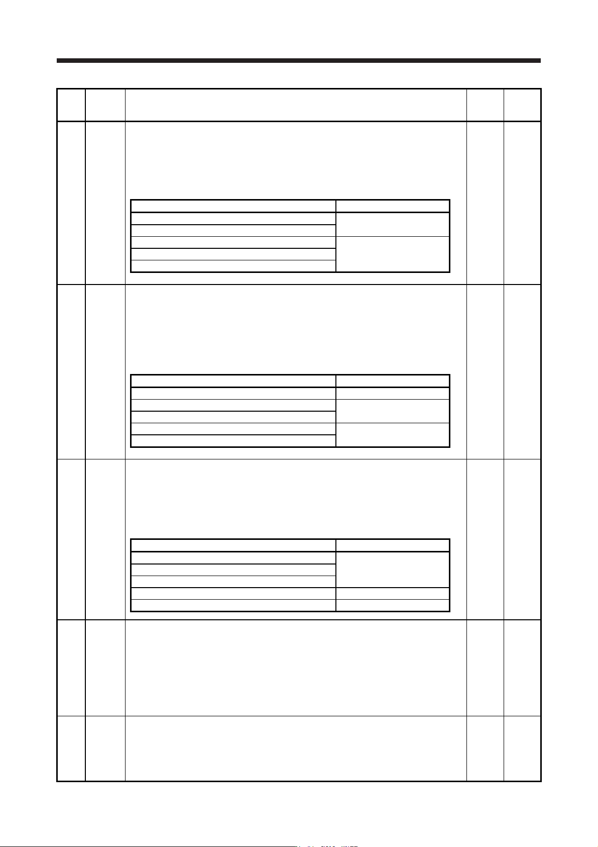
PB06 GD2 Load to motor inertia ratio/load to motor mass ratio
This is used to set the load to motor inertia ratio or load to motor mass ratio. Setting a value
considerably different from the actual load moment of inertia or load mass may cause an
unexpected operation such as an overshoot.
The setting of the parameter will be the automatic setting or manual setting depending on the
[Pr. PA08] setting. Refer to the following table for details. When the parameter is automatic
setting, the value will vary between 0.00 and 100.00.
7.00
Multiplier
0.00 to
300.00
Pr. PA08 This parameter
_ _ _ 0 (2 gain adjustment mode 1 (interpolation mode)) Automatic setting
_ _ _ 1 (Auto tuning mode 1)
_ _ _ 2 (Auto tuning mode 2) Manual setting
_ _ _ 3 (Manual mode)
_ _ _ 4 (2 gain adjustment mode 2)
PB07 PG1 Model loop gain
Set the response gain up to the target position.
Increasing the setting value will also increase the response level to the position command but
will be liable to generate vibration and noise.
For the vibration suppression control tuning mode, the setting range of [Pr. PB07] is limited.
Refer to section 7.1.5 (4) for details.
The setting of the parameter will be the automatic setting or manual setting depending on the
[Pr. PA08] setting. Refer to the following table for details.
15.0
[rad/s]
1.0 to
2000.0
Pr. PA08 This parameter
_ _ _ 0 (2 gain adjustment mode 1 (interpolation mode)) Manual setting
_ _ _ 1 (Auto tuning mode 1) Automatic setting
_ _ _ 2 (Auto tuning mode 2)
_ _ _ 3 (Manual mode) Manual setting
_ _ _ 4 (2 gain adjustment mode 2)
PB08 PG2 Position loop gain
This is used to set the gain of the position loop.
Set this parameter to increase the position response to level load disturbance.
Increasing the setting value will also increase the response level to the load disturbance but
will be liable to generate vibration and noise.
The setting of the parameter will be the automatic setting or manual setting depending on the
[Pr. PA08] setting. Refer to the following table for details.
37.0
[rad/s]
1.0 to
2000.0
Pr. PA08 This parameter
_ _ _ 0 (2 gain adjustment mode 1 (interpolation mode)) Automatic setting
_ _ _ 1 (Auto tuning mode 1)
_ _ _ 2 (Auto tuning mode 2)
_ _ _ 3 (Manual mode) Manual setting
_ _ _ 4 (2 gain adjustment mode 2) Automatic setting
PB09 VG2 Speed loop gain
This is used to set the gain of the speed loop.
Set this parameter when vibration occurs on machines of low rigidity or large backlash.
Increasing the setting value will also increase the response level but will be liable to generate
vibration and noise.
The setting of the parameter will be the automatic setting or manual setting depending on the
[Pr. PA08] setting. Refer to the table of [Pr. PB08] for details.
When the continuous operation to torque control mode is used, if the value set in this
parameter is smaller than the initial value, command torque tracking may not be successful.
823
[rad/s]
20 to
65535
PB10 VIC Speed integral compensation
This is used to set the integral time constant of the speed loop.
Decreasing the setting value will increase the response level but will be liable to generate
vibration and noise.
The setting of the parameter will be the automatic setting or manual setting depending on the
[Pr. PA08] setting. Refer to the table of [Pr. PB08] for details.
33.7
[ms]
0.1 to
1000.0
5. PARAMETERS
5 - 24
No. Symbol Name and function
Initial
value
[unit]
Setting
range
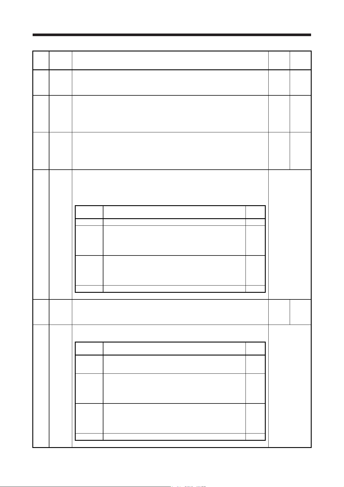
PB11 VDC Speed differential compensation
This is used to set the differential compensation.
To enable the parameter, select "Continuous PID control enabled (_ _ 3 _)" of "PI-PID
switching control selection" in [Pr. PB24].
980
0 to
1000
PB12 OVA Overshoot amount compensation
Set a dynamic friction torque in percentage to the rated torque at servo motor rated speed.
Alternatively, set a dynamic friction force in percentage to the continuous thrust at linear servo
motor rated speed.
When the response level is low or when the torque/thrust is limited, the efficiency of the
parameter may be lower.
0
[%]
0 to 100
PB13 NH1 Machine resonance suppression filter 1
Set the notch frequency of the machine resonance suppression filter 1.
When "Filter tuning mode selection" is set to "Automatic setting (_ _ _ 1)" in [Pr. PB01], this
parameter will be adjusted automatically by adaptive tuning.
When "Filter tuning mode selection" is set to "Manual setting (_ _ _ 2)" in [Pr. PB01],the
setting value will be enabled.
4500
[Hz]
10
to
4500
PB14 NHQ1 Notch shape selection 1
Set the shape of the machine resonance suppression filter 1.
When "Filter tuning mode selection" is set to "Automatic setting (_ _ _ 1)" in [Pr. PB01], this
parameter will be adjusted automatically by adaptive tuning.
To enable the setting value, select the manual setting.
Refer to the
"Name and
function" column.
Setting
digit
Explanation
Initial
value
_ _ _ x For manufacturer setting 0h
_ _ x _
Notch depth selection
0: -40 dB
1: -14 dB
2: -8 dB
3: -4 dB
0h
_ x _ _
Notch width selection
0: α = 2
1: α = 3
2: α = 4
3: α = 5
0h
x _ _ _ For manufacturer setting 0h
PB15 NH2 Machine resonance suppression filter 2
Set the notch frequency of the machine resonance suppression filter 2.
To enable the setting value, select "Enabled (_ _ _ 1)" of "Machine resonance suppression
filter 2 selection" in [Pr. PB16].
4500
[Hz]
10
to
4500
PB16 NHQ2 Notch shape selection 2
Set the shape of the machine resonance suppression filter 2.
Refer to the
"Name and
function" column.
Setting
digit
Explanation
Initial
value
_ _ _ x
Machine resonance suppression filter 2 selection
0: Disabled
1: Enabled
0h
_ _ x _
Notch depth selection
0: -40 dB
1: -14 dB
2: -8 dB
3: -4 dB
0h
_ x _ _
Notch width selection
0: α = 2
1: α = 3
2: α = 4
3: α = 5
0h
x _ _ _ For manufacturer setting 0h
5. PARAMETERS
5 - 25
No. Symbol Name and function
Initial
value
[unit]
Setting
range
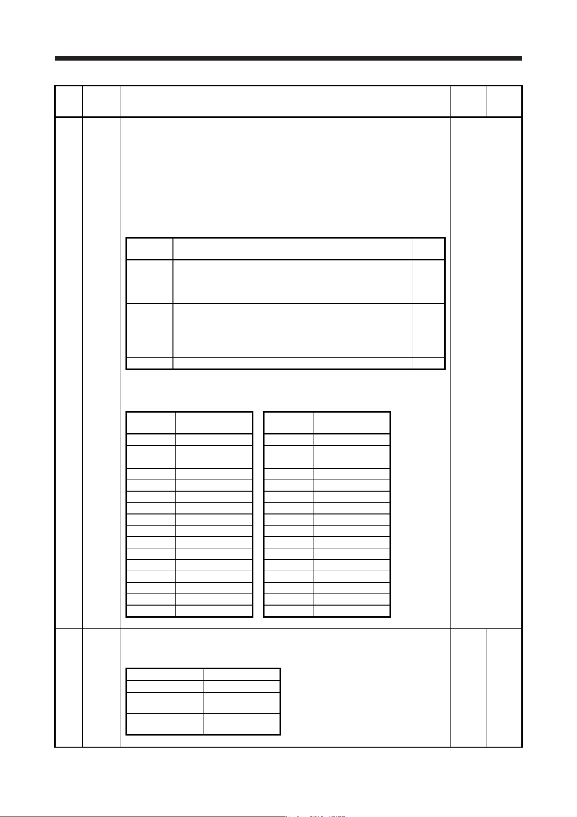
PB17 NHF Shaft resonance suppression filter
This is used for setting the shaft resonance suppression filter.
This is used to suppress a low-frequency machine vibration.
When you select "Automatic setting (_ _ _ 0)" of "Shaft resonance suppression filter selection"
in [Pr. PB23], the value will be calculated automatically from the servo motor you use and load
to motor inertia ratio. It will not automatically calculated for the linear servo motor. When
"Manual setting (_ _ _ 1)" is selected, the setting written to the parameter is used.
When "Shaft resonance suppression filter selection" is "Disabled (_ _ _ 2)" in [Pr. PB23], the
setting value of this parameter will be disabled.
When you select "Enabled (_ _ _ 1)" of "Machine resonance suppression filter 4 selection" in
[Pr. PB49], the shaft resonance suppression filter is not available.
Refer to the
"Name and
function" column.
Setting
digit
Explanation
Initial
value
_ _ x x Shaft resonance suppression filter setting frequency selection
This is used for setting the shaft resonance suppression filter.
Refer to table 5.4 for settings.
Set the value closest to the frequency you need.
00h
_ x _ _ Notch depth selection
0: -40 dB
1: -14 dB
2: -8 dB
3: -4 dB
0h
x _ _ _ For manufacturer setting 0h
Table 5.4 Shaft resonance suppression filter setting
frequency selection
Setting
value
Frequency [Hz]
Setting
value
Frequency [Hz]
_ _ 0 0 Disabled _ _ 1 0 562
_ _ 0 1 Disabled _ _ 1 1 529
_ _ 0 2 4500 _ _ 1 2 500
_ _ 0 3 3000 _ _ 1 3 473
_ _ 0 4 2250 _ _ 1 4 450
_ _ 0 5 1800 _ _ 1 5 428
_ _ 0 6 1500 _ _ 1 6 409
_ _ 0 7 1285 _ _ 1 7 391
_ _ 0 8 1125 _ _ 1 8 375
_ _ 0 9 1000 _ _ 1 9 360
_ _ 0 A 900 _ _ 1 A 346
_ _ 0 B 818 _ _ 1 B 333
_ _ 0 C 750 _ _ 1 C 321
_ _ 0 D 692 _ _ 1 D 310
_ _ 0 E 642 _ _ 1 E 300
_ _ 0 F 600 _ _ 1 F 290
PB18 LPF Low-pass filter setting
Set the low-pass filter.
The following shows a relation of a required parameter to this parameter.
3141
[rad/s]
100 to
18000
[Pr. PB23] [Pr. PB18]
_ _ 0 _ (Initial value) Automatic setting
_ _ 1 _
Setting value
enabled
_ _ 2 _
Setting value
disabled