sh030106u.pdf - 第181页
5. PARAMETE RS 5 - 36 No. Sym bol Name and function Initial value [unit] Setting range PC04 **COP1 Functi on selection C-1 Select the encoder cable c ommunication met hod. Refer to t he "Name and function" c ol…
5. PARAMETERS
5 - 35
5.2.3 Extension setting parameters ([Pr. PC_ _ ])
No. Symbol Name and function
Initial
value
[unit]
Setting
range
PC01 ERZ Error excessive alarm level
Set an error excessive alarm level.
Set this per rev. for rotary servo motors and direct drive motors. Setting "0" will be 3 rev.
Setting over 200 rev will be clamped with 200 rev.
Set this per mm for linear servo motors. Setting "0" will be 100 mm.
Refer to app. 6 for the adjustment method.
0
[rev]/
[mm]
(Note)
0 to
1000
Note. Setting can be changed in [Pr. PC06].
PC02 MBR Electromagnetic brake sequence output
This is used to set the delay time between MBR (Electromagnetic brake interlock) and the
base drive circuit is shut-off. For the timing chart of when the servo motor with an
electromagnetic brake is used, refer to section 3.10.2.
0
[ms]
0 to
1000
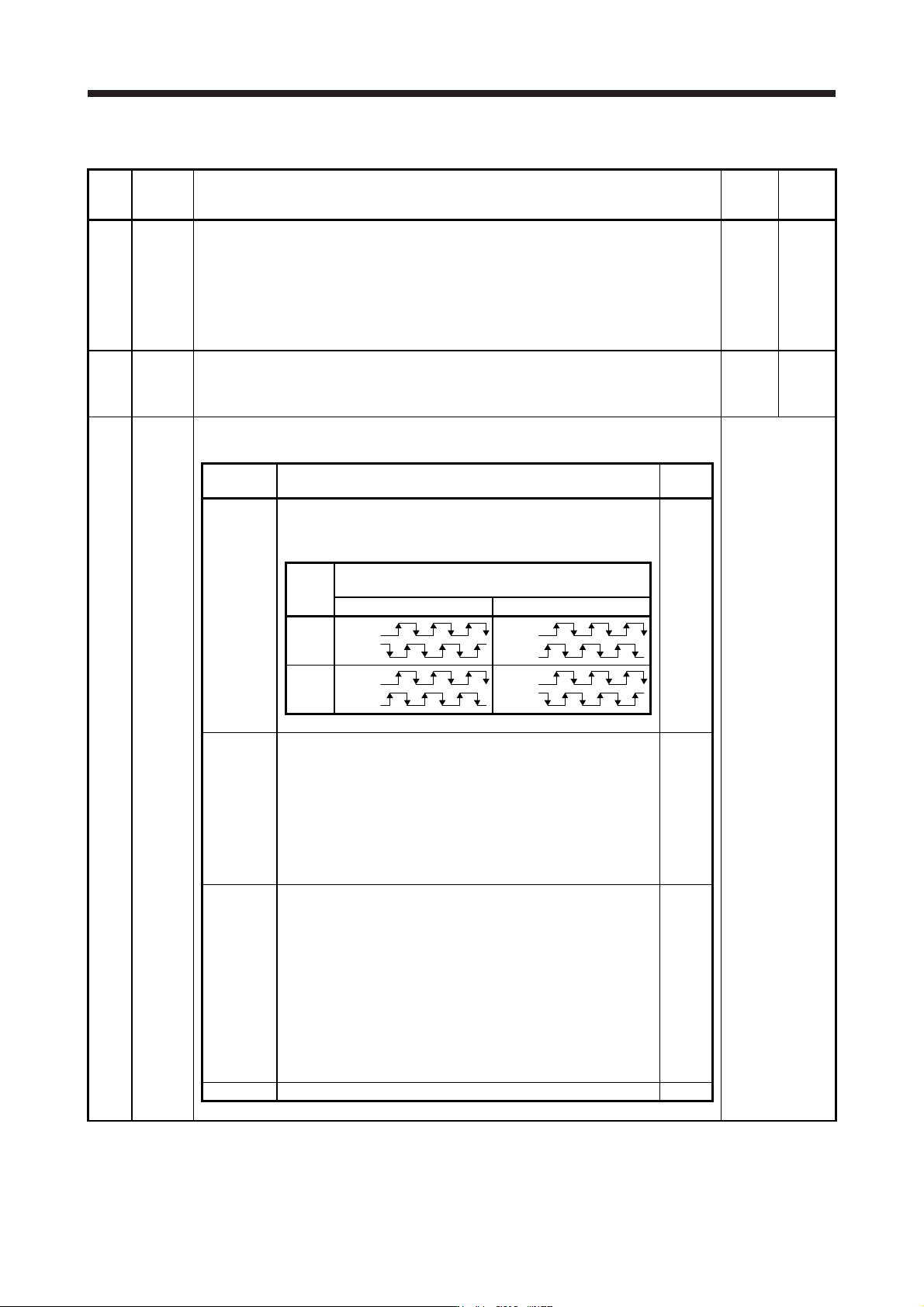
PC03 *ENRS Encoder output pulse selection
This is used to select the encoder pulse direction and encoder output pulse setting.
Refer to the
"Name and
function" column.
Setting
digit
Explanation
Initial
value
_ _ _ x Encoder output pulse phase selection
0: Increasing A-phase 90° in CCW or positive direction
1: Increasing A-phase 90° in CW or negative direction
0h
Setting
value
Servo motor rotation direction/
linear servo motor travel direction
CCW or positive direction CW or negative direction
0
A-phase
B-phase
A
-phase
B-phase
1
A-phase
B-phase
A
-phase
B-phase
_ _ x _ Encoder output pulse setting selection
Refer to app. 17 for details.
0: Output pulse setting
1: Division ratio setting
3: A-phase/B-phase pulse electronic gear setting
4: A/B-phase pulse through output setting
Depending on the servo motor stop position, the encoder output
pulse may turn on and off repeatedly even if the servo motor is
stopped.
0h
_ x _ _ Selection of the encoders for encoder output pulse
This is used for selecting an encoder for servo amplifier output.
0: Servo motor encoder
1: Load-side encoder
When "_ 1 0 _" is set to this parameter, [AL. 37 Parameter error]
will occur.
Selecting "1" in other than fully closed loop system or standard
control system (scale measurement function: enabled) triggers [AL.
37 Parameter error].
Depending on the servo motor stop position, the encoder output
pulse may turn on and off repeatedly even if the servo motor is
stopped.
0h
x _ _ _ For manufacturer setting 0h
5. PARAMETERS
5 - 36
No. Symbol Name and function
Initial
value
[unit]
Setting
range
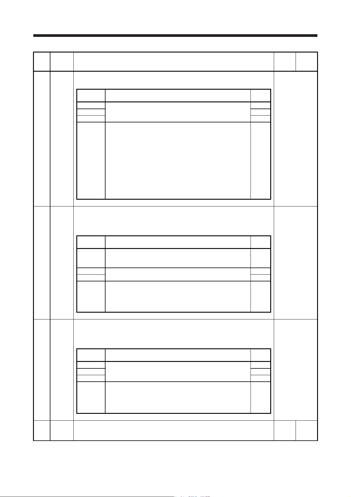
PC04 **COP1 Function selection C-1
Select the encoder cable communication method.
Refer to the
"Name and
function" column.
Setting
digit
Explanation
Initial
value
_ _ _ x For manufacturer setting 0h
_ _ x _ 0h
_ x _ _ 0h
x _ _ _ Encoder cable communication method selection
0: Two-wire type
1: Four-wire type
When using an encoder of A/B/Z-phase differential output method,
set "0".
Incorrect setting will result in [AL. 16 Encoder initial communication
error 1] or [AL. 20 Encoder normal communication error 1]. Setting
"1" will trigger [AL. 37] while "Fully closed loop control mode (_ _ 1
_)" is selected in [Pr. PA01] (except MR-J4-_B_-RJ).
If the settings of the servo amplifier are unchanged from the factory
settings and communication with the controller is performed for the
first time, this digit will be automatically set according to the
communication method of the connected encoder cable.
0h
PC05 **COP2 Function selection C-2
Set the motor-less operation and [AL. 9B Error excessive warning]. The motor-less operation
cannot be used in the fully closed loop control mode, linear servo motor control mode, or DD
motor control mode.
Refer to the
"Name and
function" column.
Setting
digit
Explanation
Initial
value
_ _ _ x Motor-less operation selection
0: Disabled
1: Enabled
0h
_ _ x _ For manufacturer setting 0h
_ x _ _ 0h
x _ _ _ [AL. 9B Error excessive warning] selection
0: [AL. 9B Error excessive warning] disabled
1: [AL. 9B Error excessive warning] enabled
The setting of this digit is used by servo amplifier with software
version B4 or later.
0h
PC06 *COP3 Function selection C-3
Select units for error excessive alarm level setting with [Pr. PC01] and for error excessive
warning level setting with [Pr. PC38]. The parameter is not available in the speed control
mode and torque control mode.
Refer to the
"Name and
function" column.
Setting
digit
Explanation
Initial
value
_ _ _ x For manufacturer setting 0h
_ _ x _ 0h
_ x _ _ 0h
x _ _ _ Error excessive alarm/error excessive warning level unit selection
0: Per 1 rev or 1 mm
1: Per 0.1 rev or 0.1 mm
2: Per 0.01 rev or 0.01 mm
3: Per 0.001 rev or 0.001 mm
0h
PC07 ZSP Zero speed
Used to set the output range of ZSP (Zero speed detection).
ZSP (Zero speed detection) has hysteresis of 20 r/min or 20 mm/s.
50
[r/min]/
[mm/s]
0
to
10000
5. PARAMETERS
5 - 37
No. Symbol Name and function
Initial
value
[unit]
Setting
range
PC08 OSL Overspeed alarm detection level
This is used to set an overspeed alarm detection level.
When you set a value more than "servo motor maximum speed × 120%" or "linear servo
motor maximum speed × 120%", the set value will be clamped.
When you set "0", the value of "(linear) servo motor maximum speed × 120%" will be set.
0
[r/min]/
[mm/s]
0
to
20000
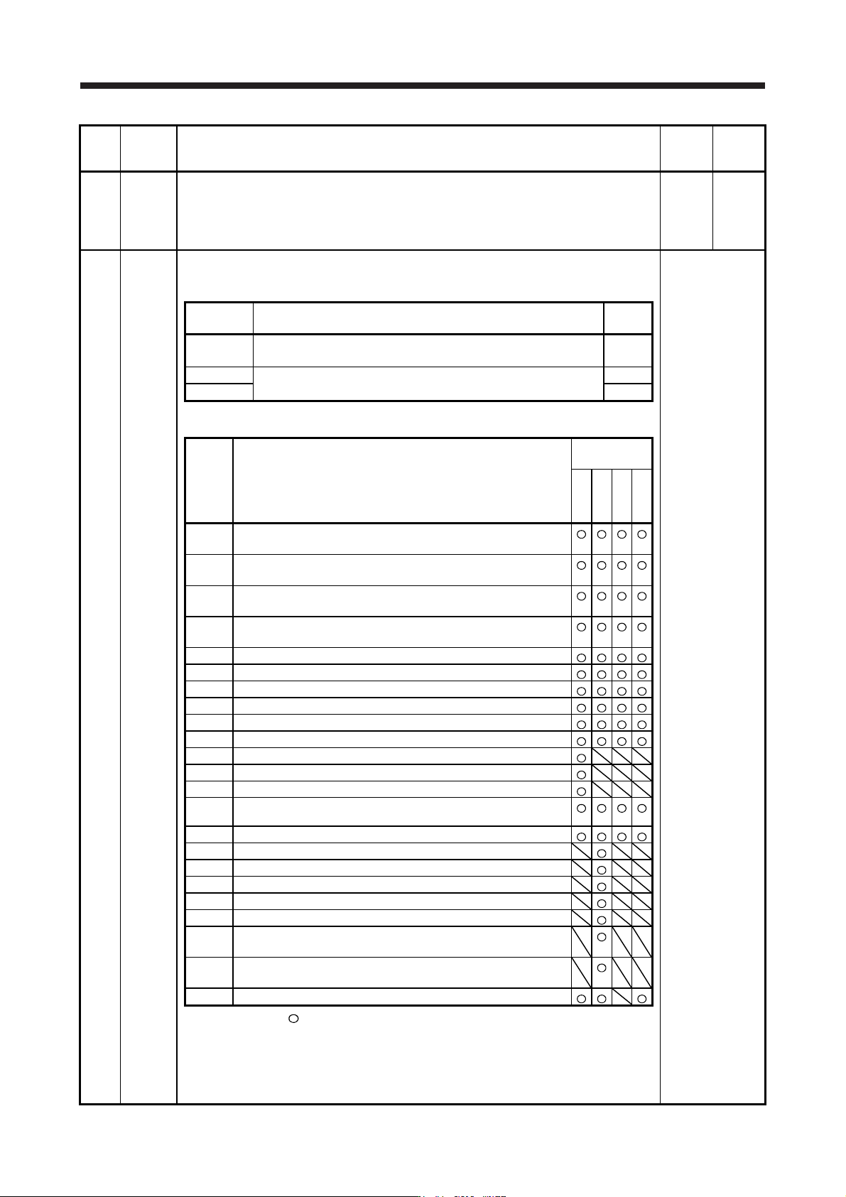
PC09 MOD1 Analog monitor 1 output
Select a signal to output to MO1 (Analog monitor 1). Refer to app. 11.3 for detection point of
output selection.
Refer to the
"Name and
function" column.
Setting
digit
Explanation
Initial
value
_ _ x x Analog monitor 1 output selection
Refer to table 5.7 for settings.
00h
_ x _ _ For manufacturer setting 0h
x _ _ _ 0h
Table 5.7 Analog monitor setting value
Setting
value
Item
Operation
mode (Note 1)
Standard
Full.
Lin.
D.D.
_ _ 0 0
(Linear) servo motor speed
(±8 V/max. speed)
_ _ 0 1
Torque or thrust
(±8 V/max. torque or max. thrust)
_ _ 0 2
(Linear) servo motor speed
(+8 V/max. speed)
_ _ 0 3
Torque or thrust
(+8 V/max. torque or max. thrust)
_ _ 0 4 Current command (±8 V/max. current command)
_ _ 0 5 Speed command (±8 V/max. speed)
_ _ 0 6 Servo motor-side droop pulses (±10 V/100 pulses) (Note 2)
_ _ 0 7 Servo motor-side droop pulses (±10 V/1000 pulses) (Note 2)
_ _ 0 8 Servo motor-side droop pulses (±10 V/10000 pulses) (Note 2)
_ _ 0 9 Servo motor-side droop pulses (±10 V/100000 pulses) (Note 2)
_ _ 0 A Feedback position (±10 V/1 Mpulse) (Note 2)
_ _ 0 B Feedback position (±10 V/10 Mpulses) (Note 2)
_ _ 0 C Feedback position (±10 V/100 Mpulses) (Note 2)
_ _ 0 D
Bus voltage (200 V class and 100 V class: +8 V/400 V, 400 V
class: +8 V/800 V)
_ _ 0 E Speed command 2 (±8 V/max. speed)
_ _ 1 0 Load-side droop pulses (±10 V/100 pulses) (Note 2)
_ _ 1 1 Load-side droop pulses (±10 V/1000 pulses) (Note 2)
_ _ 1 2 Load-side droop pulses (±10 V/10000 pulses) (Note 2)
_ _ 1 3 Load-side droop pulses (±10 V/100000 pulses) (Note 2)
_ _ 1 4 Load-side droop pulses (±10 V/1 Mpulse) (Note 2)
_ _ 1 5
Servo motor-side/load-side position deviation
(±10 V/100000 pulses)
_ _ 1 6
Servo motor-side/load-side speed deviation
(±8 V/max. speed)
_ _ 1 7 Internal temperature of encoder (±10 V/±128 ˚C)
Note 1. Items with
are available for each operation mode.
Standard: Semi closed loop system use of the rotary servo motor
Full.: Fully closed loop system use of the rotary servo motor
Lin.: Linear servo motor use
D.D.: Direct drive motor use
2. Encoder pulse unit