sh030106u.pdf - 第183页
5. PARAMETE RS 5 - 38 No. Sym bol Name and function Initial value [unit] Setting range PC10 MOD2 Analog monitor 2 output Select a signal to out put to MO2 (Analog m onitor 2). Refer to app. 11.3 for detection poi nt of o…
5. PARAMETERS
5 - 37
No. Symbol Name and function
Initial
value
[unit]
Setting
range
PC08 OSL Overspeed alarm detection level
This is used to set an overspeed alarm detection level.
When you set a value more than "servo motor maximum speed × 120%" or "linear servo
motor maximum speed × 120%", the set value will be clamped.
When you set "0", the value of "(linear) servo motor maximum speed × 120%" will be set.
0
[r/min]/
[mm/s]
0
to
20000
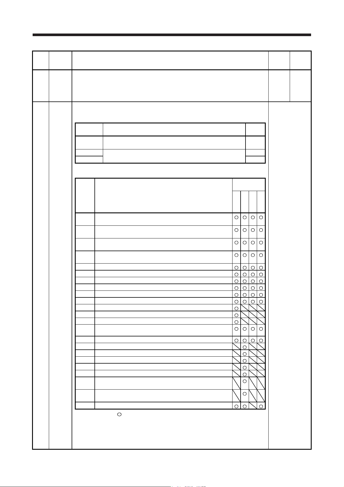
PC09 MOD1 Analog monitor 1 output
Select a signal to output to MO1 (Analog monitor 1). Refer to app. 11.3 for detection point of
output selection.
Refer to the
"Name and
function" column.
Setting
digit
Explanation
Initial
value
_ _ x x Analog monitor 1 output selection
Refer to table 5.7 for settings.
00h
_ x _ _ For manufacturer setting 0h
x _ _ _ 0h
Table 5.7 Analog monitor setting value
Setting
value
Item
Operation
mode (Note 1)
Standard
Full.
Lin.
D.D.
_ _ 0 0
(Linear) servo motor speed
(±8 V/max. speed)
_ _ 0 1
Torque or thrust
(±8 V/max. torque or max. thrust)
_ _ 0 2
(Linear) servo motor speed
(+8 V/max. speed)
_ _ 0 3
Torque or thrust
(+8 V/max. torque or max. thrust)
_ _ 0 4 Current command (±8 V/max. current command)
_ _ 0 5 Speed command (±8 V/max. speed)
_ _ 0 6 Servo motor-side droop pulses (±10 V/100 pulses) (Note 2)
_ _ 0 7 Servo motor-side droop pulses (±10 V/1000 pulses) (Note 2)
_ _ 0 8 Servo motor-side droop pulses (±10 V/10000 pulses) (Note 2)
_ _ 0 9 Servo motor-side droop pulses (±10 V/100000 pulses) (Note 2)
_ _ 0 A Feedback position (±10 V/1 Mpulse) (Note 2)
_ _ 0 B Feedback position (±10 V/10 Mpulses) (Note 2)
_ _ 0 C Feedback position (±10 V/100 Mpulses) (Note 2)
_ _ 0 D
Bus voltage (200 V class and 100 V class: +8 V/400 V, 400 V
class: +8 V/800 V)
_ _ 0 E Speed command 2 (±8 V/max. speed)
_ _ 1 0 Load-side droop pulses (±10 V/100 pulses) (Note 2)
_ _ 1 1 Load-side droop pulses (±10 V/1000 pulses) (Note 2)
_ _ 1 2 Load-side droop pulses (±10 V/10000 pulses) (Note 2)
_ _ 1 3 Load-side droop pulses (±10 V/100000 pulses) (Note 2)
_ _ 1 4 Load-side droop pulses (±10 V/1 Mpulse) (Note 2)
_ _ 1 5
Servo motor-side/load-side position deviation
(±10 V/100000 pulses)
_ _ 1 6
Servo motor-side/load-side speed deviation
(±8 V/max. speed)
_ _ 1 7 Internal temperature of encoder (±10 V/±128 ˚C)
Note 1. Items with
are available for each operation mode.
Standard: Semi closed loop system use of the rotary servo motor
Full.: Fully closed loop system use of the rotary servo motor
Lin.: Linear servo motor use
D.D.: Direct drive motor use
2. Encoder pulse unit
5. PARAMETERS
5 - 38
No. Symbol Name and function
Initial
value
[unit]
Setting
range
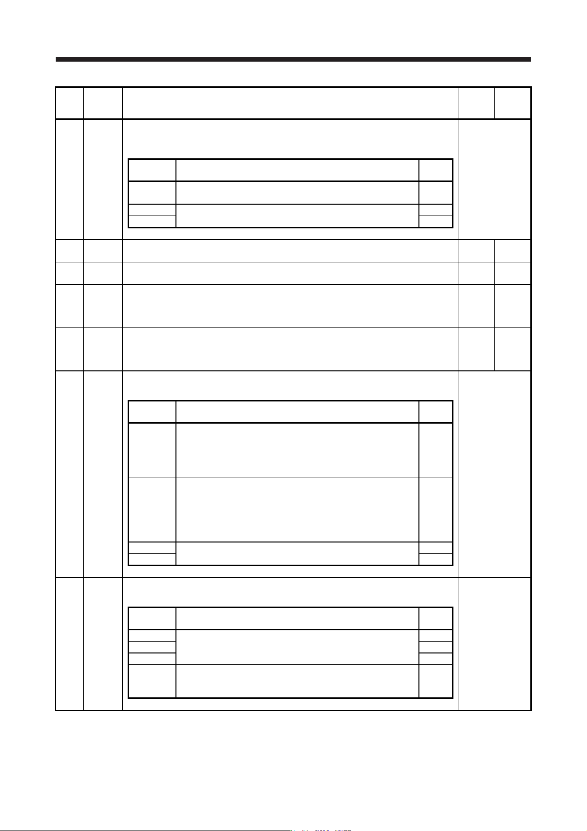
PC10 MOD2 Analog monitor 2 output
Select a signal to output to MO2 (Analog monitor 2). Refer to app. 11.3 for detection point of
output selection.
Refer to the
"Name and
function" column.
Setting
digit
Explanation
Initial
value
_ _ x x
Analog monitor 2 output selection
Refer to [Pr. PC09] for settings.
01h
_ x _ _ For manufacturer setting 0h
x _ _ _ 0h
PC11 MO1 Analog monitor 1 offset
This is used to set the offset voltage of MO1 (Analog monitor 1).
0
[mV]
-999 to
999
PC12 MO2 Analog monitor 2 offset
This is used to set the offset voltage of MO2 (Analog monitor 2).
0
[mV]
-999 to
999
PC13 MOSDL Analog monitor - Feedback position output standard data - Low
Set a monitor output standard position (lower 4 digits) for the feedback position for when
selecting "Feedback position" for MO1 (Analog monitor 1) and MO2 (Analog monitor 2).
Monitor output standard position = [Pr. PC14] setting × 10000 + [Pr. PC13] setting
0
[pulse]
-9999 to
9999
PC14 MOSDH Analog monitor - Feedback position output standard data - High
Set a monitor output standard position (higher 4 digits) for the feedback position for when
selecting "Feedback position" for MO1 (Analog monitor 1) and MO2 (Analog monitor 2).
Monitor output standard position = [Pr. PC14] setting × 10000 + [Pr. PC13] setting
0
[10000
pulses]
-9999 to
9999
PC17 **COP4 Function selection C-4
This is used to select a home position setting condition.
Refer to the
"Name and
function" column.
Setting
digit
Explanation
Initial
value
_ _ _ x
Selection of home position setting condition
When using an incremental type linear encoder, set "0". Setting "1"
triggers [AL. 37 Parameter error].
0: Need to pass servo motor Z-phase after power on
1: Not need to pass servo motor Z-phase after power on
0h
_ _ x _ Linear encoder multipoint Z-phase input function selection
When two or more reference marks exist in the fully stroke, set "1".
0: Disabled
1: Enabled
This parameter is used by servo amplifier with software version A5
or later.
0h
_ x _ _ For manufacturer setting 0h
x _ _ _ 0h
PC18 *COP5 Function selection C-5
This is used to select an occurring condition of [AL. E9 Main circuit off warning].
Refer to the
"Name and
function" column.
Setting
digit
Explanation
Initial
value
_ _ _ x For manufacturer setting 0h
_ _ x _ 0h
_ x _ _ 0h
x _ _ _
[AL. E9 Main circuit off warning] selection
0: Detection with ready-on and servo-on command
1: Detection with servo-on command
0h

5. PARAMETERS
5 - 39
No. Symbol Name and function
Initial
value
[unit]
Setting
range
PC20 *COP7 Function selection C-7
This is used to select an undervoltage alarm detection method.
Refer to the
"Name and
function" column.
Setting
digit
Explanation
Initial
value
_ _ _ x
[AL. 10 Undervoltage] detection method selection
If [AL. 10 Undervoltage] occurs due to power supply voltage
distortion while FR-RC-(H), FR-CV-(H), or FR-XC-(H) is being used,
use this setting.
0: When [AL. 10] does not occur
1: When [AL. 10] occurs
When using the MR-J4-_B-RJ servo amplifier with the DC power
supply input, set "1".
0h
_ _ x _ For manufacturer setting 0h
_ x _ _ Undervoltage alarm selection
Select the alarm and warning for when the bus voltage drops to the
undervoltage alarm level.
0: [AL. 10] regardless of servo motor speed
1: [AL. E9] at servo motor speed 50 r/min (50 mm/s) or less, [AL.
10] at over 50 r/min (50 mm/s)
0h
x _ _ _ For manufacturer setting 0h
PC21 *BPS Alarm history clear
Used to clear the alarm history.
Refer to the
"Name and
function" column.
Setting
digit
Explanation
Initial
value
_ _ _ x Alarm history clear selection
0: Disabled
1: Enabled
When "Enabled" is set, the alarm history will be cleared at the next
power-on. Once the alarm history is cleared, the setting becomes
disabled automatically.
0h
_ _ x _ For manufacturer setting 0h
_ x _ _ 0h
x _ _ _ 0h