sh030106u.pdf - 第184页
5. PARAMETE RS 5 - 39 No. Sym bol Name and function Initial value [unit] Setting range PC20 *COP7 Funct ion selection C-7 This is us ed to select an undervoltage alarm det ection method. Refer to t he "Name and func…
5. PARAMETERS
5 - 38
No. Symbol Name and function
Initial
value
[unit]
Setting
range
PC10 MOD2 Analog monitor 2 output
Select a signal to output to MO2 (Analog monitor 2). Refer to app. 11.3 for detection point of
output selection.
Refer to the
"Name and
function" column.
Setting
digit
Explanation
Initial
value
_ _ x x
Analog monitor 2 output selection
Refer to [Pr. PC09] for settings.
01h
_ x _ _ For manufacturer setting 0h
x _ _ _ 0h
PC11 MO1 Analog monitor 1 offset
This is used to set the offset voltage of MO1 (Analog monitor 1).
0
[mV]
-999 to
999
PC12 MO2 Analog monitor 2 offset
This is used to set the offset voltage of MO2 (Analog monitor 2).
0
[mV]
-999 to
999
PC13 MOSDL Analog monitor - Feedback position output standard data - Low
Set a monitor output standard position (lower 4 digits) for the feedback position for when
selecting "Feedback position" for MO1 (Analog monitor 1) and MO2 (Analog monitor 2).
Monitor output standard position = [Pr. PC14] setting × 10000 + [Pr. PC13] setting
0
[pulse]
-9999 to
9999
PC14 MOSDH Analog monitor - Feedback position output standard data - High
Set a monitor output standard position (higher 4 digits) for the feedback position for when
selecting "Feedback position" for MO1 (Analog monitor 1) and MO2 (Analog monitor 2).
Monitor output standard position = [Pr. PC14] setting × 10000 + [Pr. PC13] setting
0
[10000
pulses]
-9999 to
9999
PC17 **COP4 Function selection C-4
This is used to select a home position setting condition.
Refer to the
"Name and
function" column.
Setting
digit
Explanation
Initial
value
_ _ _ x
Selection of home position setting condition
When using an incremental type linear encoder, set "0". Setting "1"
triggers [AL. 37 Parameter error].
0: Need to pass servo motor Z-phase after power on
1: Not need to pass servo motor Z-phase after power on
0h
_ _ x _ Linear encoder multipoint Z-phase input function selection
When two or more reference marks exist in the fully stroke, set "1".
0: Disabled
1: Enabled
This parameter is used by servo amplifier with software version A5
or later.
0h
_ x _ _ For manufacturer setting 0h
x _ _ _ 0h
PC18 *COP5 Function selection C-5
This is used to select an occurring condition of [AL. E9 Main circuit off warning].
Refer to the
"Name and
function" column.
Setting
digit
Explanation
Initial
value
_ _ _ x For manufacturer setting 0h
_ _ x _ 0h
_ x _ _ 0h
x _ _ _
[AL. E9 Main circuit off warning] selection
0: Detection with ready-on and servo-on command
1: Detection with servo-on command
0h
5. PARAMETERS
5 - 39
No. Symbol Name and function
Initial
value
[unit]
Setting
range
PC20 *COP7 Function selection C-7
This is used to select an undervoltage alarm detection method.
Refer to the
"Name and
function" column.
Setting
digit
Explanation
Initial
value
_ _ _ x
[AL. 10 Undervoltage] detection method selection
If [AL. 10 Undervoltage] occurs due to power supply voltage
distortion while FR-RC-(H), FR-CV-(H), or FR-XC-(H) is being used,
use this setting.
0: When [AL. 10] does not occur
1: When [AL. 10] occurs
When using the MR-J4-_B-RJ servo amplifier with the DC power
supply input, set "1".
0h
_ _ x _ For manufacturer setting 0h
_ x _ _ Undervoltage alarm selection
Select the alarm and warning for when the bus voltage drops to the
undervoltage alarm level.
0: [AL. 10] regardless of servo motor speed
1: [AL. E9] at servo motor speed 50 r/min (50 mm/s) or less, [AL.
10] at over 50 r/min (50 mm/s)
0h
x _ _ _ For manufacturer setting 0h
PC21 *BPS Alarm history clear
Used to clear the alarm history.
Refer to the
"Name and
function" column.
Setting
digit
Explanation
Initial
value
_ _ _ x Alarm history clear selection
0: Disabled
1: Enabled
When "Enabled" is set, the alarm history will be cleared at the next
power-on. Once the alarm history is cleared, the setting becomes
disabled automatically.
0h
_ _ x _ For manufacturer setting 0h
_ x _ _ 0h
x _ _ _ 0h
5. PARAMETERS
5 - 40
No. Symbol Name and function
Initial
value
[unit]
Setting
range
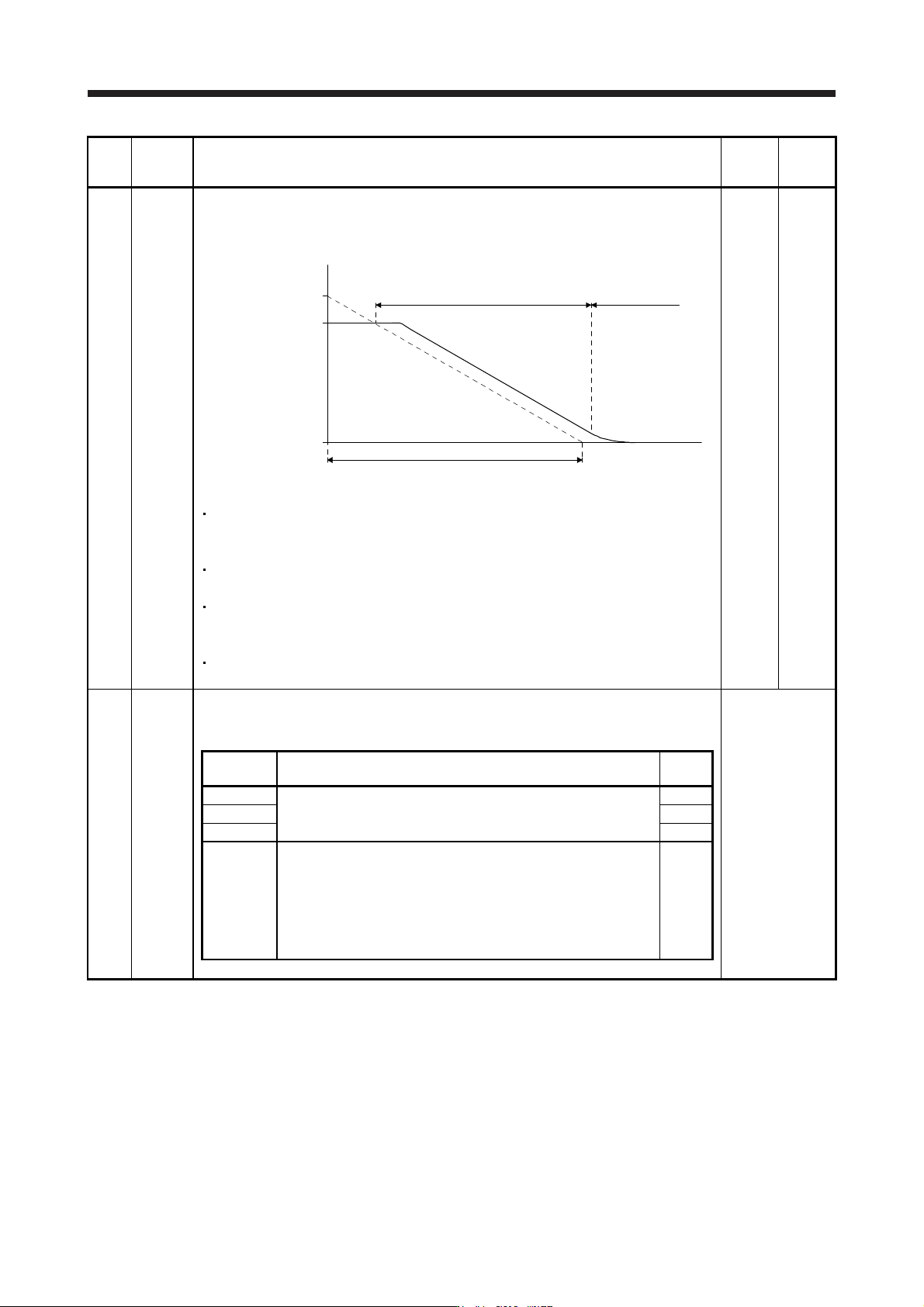
PC24 RSBR Forced stop deceleration time constant
This is used to set deceleration time constant when you use the forced stop deceleration
function.
Set the time per ms from the rated speed to 0 r/min or 0 mm/s. Setting "0" will be 100 ms.
Forced stop deceleration
[Pr. PC24]
0 r/min
(0 mm/s)
Servo motor speed
Rated speed
Dynamic brake
deceleration
(Linear servo motor
speed)
[Precautions]
If the servo motor torque or linear servo motor thrust is saturated at the maximum torque
during forced stop deceleration because the set time is too short, the time to stop will be
longer than the set time constant.
[AL. 50 Overload alarm 1] or [AL. 51 Overload alarm 2] may occur during forced stop
deceleration, depending on the set value.
After an alarm that leads to a forced stop deceleration, if an alarm that does not lead to a
forced stop deceleration occurs or if the control circuit power supply is cut, dynamic braking
will start regardless of the deceleration time constant setting.
Set a longer time than deceleration time at quick stop of the controller. If a shorter time is
set, [AL. 52 Error excessive] ma
y
occur.
100
[ms]
0 to
20000
PC26 **COP8 Function selection C-8
Used to select the communication method of the encoder cable to be connected to the CN2L
connector of MR-J4-_B_-RJ.
Refer to the
"Name and
function" column.
Setting
digit
Explanation
Initial
value
_ _ _ x For manufacturer setting 0h
_ _ x _ 0h
_ x _ _ 0h
x _ _ _ Load-side encoder communication method
0: Two-wire type
1: Four-wire type
When using a load-side encoder of A/B/Z-phase differential output
method, set "0".
Setting "1" by using a servo amplifier other than MR-J4-_B_-RJ will
trigger [AL. 37].
0h